
Adjustable medical magnifier

A magnifying glass and adjustable technology, which is applied in the field of medical devices, can solve the problems of long time to hold a magnifying glass stably, numerous resolution steps, difficulty in ensuring stability, etc., and achieve the effects of improving portability, expanding the scope of application, and improving space utilization

Pending Publication Date: 2022-08-09
徐州蓝色电子科技有限公司
View PDF0 Cites 0 Cited by
  • Summary
  • Abstract
  • Description
  • Claims
  • Application Information

AI Technical Summary

Problems solved by technology

[0003] The purpose of the present invention is to provide an adjustable medical magnifying glass to solve the problem that most of the existing medical magnifying glasses proposed in the above background technology are simple in structure, that is, the magnifying glass needs to be manually held when the medical staff observes the affected area, and at the same time due to skin diseases There are many steps to distinguish and many different symptoms may appear. Therefore, it takes a long time to hold the magnifying glass stably, and it is difficult to ensure stability when holding it for a long time artificially, and it is more laborious.

Method used


Image

  • Adjustable medical magnifier
  • Adjustable medical magnifier
  • Adjustable medical magnifier

Examples


Embodiment Construction

[0036] The technical solutions in the embodiments of the present invention will be clearly and completely described below with reference to the accompanying drawings in the embodiments of the present invention. Obviously, the described embodiments are only a part of the embodiments of the present invention, but not all of the embodiments. Based on the embodiments of the present invention, all other embodiments obtained by those of ordinary skill in the art without creative efforts shall fall within the protection scope of the present invention.

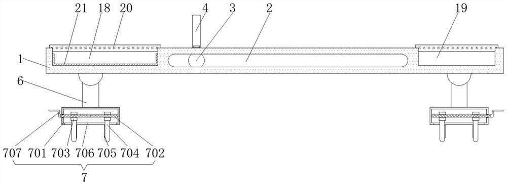
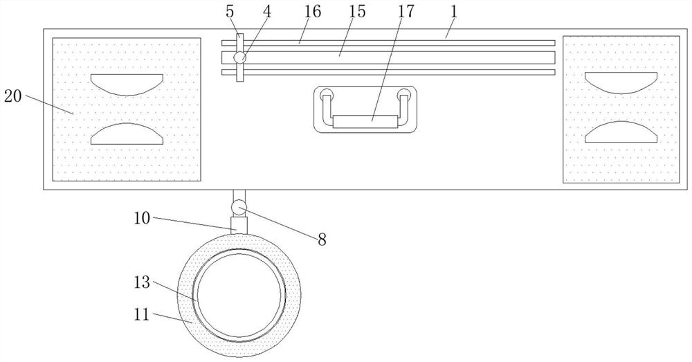
[0037] see Figure 1-6 , the present invention provides a technical solution: an adjustable medical magnifying glass, such as figure 1 , figure 2 , image 3 and Figure 4 As shown, the side of the carrying plate 1 is provided with an adjusting groove 2, and the adjusting groove 2 is provided with a sliding rod 3, and at the same time one end of the sliding rod 3 is connected with the handle 4, and the handle 4 penetrates the guide...


PUM


Abstract

The invention discloses an adjustable medical magnifier which comprises a bearing plate, a clamping assembly, a first storage groove and a second storage groove, an adjusting groove is formed in the side face of the bearing plate, a sliding rod is arranged in the adjusting groove, the other end of the sliding rod is connected with one end of an electric telescopic rod, and a lamp assembly is arranged at the bottom of a lamp holder. A medical magnifying glass body is connected to the inner side of the lamp holder, and the clamping assemblies are symmetrically arranged at the bottom of the bearing plate. According to the adjustable medical magnifier, the clamping assembly and the electric telescopic rod are arranged, so that a person can fix the device on a handrail on the side face of a sickbed through the clamping assembly, the position of the medical magnifier body can be fixed, and labor is saved compared with manual holding; and meanwhile, a worker can turn over supporting legs at the top of the clamping assembly when the device is not used, so that the clamping assembly can be folded and stored at the bottom of the bearing plate, the structure of the device is optimized conveniently, and meanwhile the portability of the device is improved.

Description

technical field [0001] The invention relates to the technical field of medical devices, in particular to an adjustable medical magnifying glass. Background technique [0002] A simple visual optical device used by a magnifying glass to observe the minute details of an object, it is a converging lens with a focal length much smaller than the eye's photopic distance. The size of the image of the object on the retina of the human eye is proportional to the angle (viewing angle) of the object to the eye. The medical magnifying glass is a low-power microscope device. In the process of dermatology diagnosis and treatment of some skin diseases, a magnifying glass needs to be used for its fine-tuning. It is convenient to prevent medical staff from misdiagnosing due to the numerous and similar symptoms, and then to prescribe the right medicine. Most of the existing medical magnifiers are simple in structure, that is, when medical staff observe the affected area, the magnifying glass...

Claims


Application Information

Patent Timeline
Patent Type & Authority Applications(China)
IPC IPC(8): A61B90/00A61B90/30
CPCA61B90/361A61B90/30A61B2090/3616
Inventor 吕明亮刘卿颖李祖耀
Owner 徐州蓝色电子科技有限公司
Learn More