Bending machine controller mounting mechanism capable of being quickly disassembled and assembled

A technology for installing mechanisms and controllers, applied in the direction of supporting machines, mechanical equipment, etc., can solve problems such as unfavorable high-efficiency production, cumbersome operation of the moving position of the controller, etc., and achieve the effect of convenient device loading and unloading, convenient loading and unloading, and fast loading and unloading

Pending Publication Date: 2021-12-10
CHANGZHOU ZHONGYAN TECH DEV
View PDF0 Cites 0 Cited by
  • Summary
  • Abstract
  • Description
  • Claims
  • Application Information

AI Technical Summary

Problems solved by technology

[0002] The bending machine is suitable for processing rods and is a kind of equipment for bending rods at a limited angle. In order to meet the needs of numerical control production, the bending machine in the prior art is also equipped with an electronic controller on its control structure to facilitate bending. The bending machine can operate according to the preset parameters to ensure the assembly line industrial production; when some miniaturized bending machines are in use, in order to save the volume of the equipment, the controller will be set as an active structure. According to the different workpieces, it can be Adjust the position of the controller and remove the equipment panel to place the workpiece, which requires loading and unloading of multi-point fixed structures when changing the position of the controller, making the operation of moving the position of the controller too cumbersome and not conducive to efficient production, so now a This kind of mechanism can be applied to this type of bending machine to fix the controller, and can avoid the above disadvantages

Method used


Image

  • Bending machine controller mounting mechanism capable of being quickly disassembled and assembled
  • Bending machine controller mounting mechanism capable of being quickly disassembled and assembled
  • Bending machine controller mounting mechanism capable of being quickly disassembled and assembled

Examples


specific Embodiment approach 1

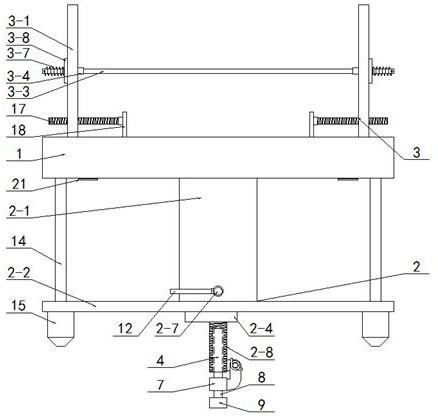
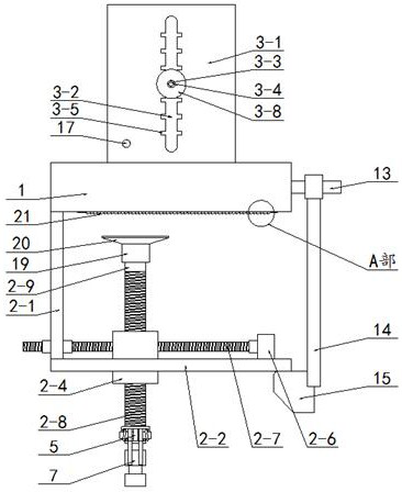
[0029] Such as Figure 1-Figure 7As shown, this specific embodiment adopts the following technical scheme: including a mounting base 1, a fixing component 2, and a connecting component 3, wherein the fixing component 2 is riveted on the lower surface of the mounting base 1, and the mounting base 1 is connected to the external machine through the fixing component 2. The frame is connected and set, the connecting assembly 3 is riveted on the upper surface of the mounting seat 1, and the lower surface of the mounting seat 1 is riveted with a rubber rack 21, and the lower end of the tooth of the rubber rack 21 is inclined forward. When placed on the frame, the mounting seat 1 is pressed against the upper surface of the frame through the rubber rack 21, and then the rubber rack 21 prevents the frame from sliding forward. To increase the frictional force when sliding forward, if a forward force is generated at this time, the rubber rack 21 will deform and further press against the f...

Embodiment 1

[0036] When fixing the mounting seat 1 and the frame, mount the mounting seat 1 on the panel of the frame, rotate the vertical threaded rod 2-8, and mount it up and down on the panel of the frame through the mounting seat 1 and the top block 2-9 On both sides, realize the clamping and fixing of the mounting base 1:

Embodiment 2

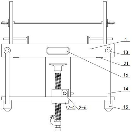
[0038] When fixing the mounting base 1 and the frame, mount the mounting base 1 on the rod of the frame, rotate the vertical threaded rod 2-8 so that the stopper 9 is located at the rear of the rod, and rotate the horizontal threaded rod 2-8 7 Move the fixed seat 2-4 forward, and then the connecting plate 2-1 and the top block 2-9 are mounted on the front and rear sides of the bar, so that the top block 2-9 is pressed against the rear side wall of the bar, and the connecting plate 2-9 1 against the front side wall of the rod, and clamp and fix the mounting base 1.

[0039] After adopting the above structure, the beneficial effects of this embodiment are as follows:

[0040] 1. The lower part of the mounting seat 1 is connected with the connecting plate 2-1 and the riveting plate 2-2 is set, and the fixing seat 2-4 is set on the riveting plate 2-2 through the No. 1 waist-shaped hole 2-3, and the fixing seat 2-4 is Set the horizontal threaded rod 2-7, the vertical threaded rod ...


PUM


Abstract

The invention discloses a bending machine controller mounting mechanism capable of being quickly disassembled and assembled, and relates to the technical field of bending machine structures. The bending machine controller mounting mechanism capable of being quickly disassembled and assembled comprises a mounting seat, a fixing assembly and a connecting assembly, the fixing assembly is fixedly arranged on the lower surface of the mounting seat, the mounting seat is connected with an external rack through the fixing assembly, and the connecting assembly is fixedly arranged on the upper surface of the mounting seat. According to the bending machine controller mounting mechanism capable of being quickly disassembled and assembled, threaded rod structures in the transverse direction and the longitudinal direction are arranged, then the longitudinal threaded rod is matched with the mounting seat to abut against and fix the mounting seat on the rack, meanwhile, the position of an abutting point can be adjusted through the transverse threaded rod, and then the clamping position of the mounting seat can be adaptively adjusted according to racks of different models; and a structure for clamping and pressing is arranged, therefore, a controller can be conveniently arranged on the mounting seat and fixed, and the clamping structure is convenient to assemble and disassemble.

Description

technical field [0001] The invention relates to the technical field of bending machine structures, in particular to a fast dismountable bending machine controller installation mechanism. Background technique [0002] The bending machine is suitable for processing rods and is a kind of equipment for bending rods at a limited angle. In order to meet the needs of numerical control production, the bending machine in the prior art is also equipped with an electronic controller on its control structure to facilitate bending. The bending machine can operate according to the preset parameters to ensure the assembly line industrial production; when some miniaturized bending machines are in use, in order to save the volume of the equipment, the controller will be set as an active structure. According to the different workpieces, it can be Adjust the position of the controller and remove the equipment panel to place the workpiece, which requires loading and unloading of multi-point fix...

Claims


Application Information

Patent Timeline
IPC IPC(8): B21D7/16F16M13/02
CPCB21D7/16F16M13/022
Inventor 朱化吉尹澄析邱合群尹柏求
Owner CHANGZHOU ZHONGYAN TECH DEV
Why Eureka
Try Eureka