An electric shock type mosquito and fly trap

A technology of mosquitoes and flies and conductive grooves, which is applied in the fields of trapping or killing insects, applications, animal husbandry, etc. It can solve the problems of electrode wire grid short circuit, potential safety hazards, electric shock killing of mosquitoes and flies, etc., and prolong the service life , Prevent unconscious electric shock, high safety effect

Active Publication Date: 2018-06-12
赖信
View PDF8 Cites 0 Cited by
  • Summary
  • Abstract
  • Description
  • Claims
  • Application Information

AI Technical Summary

Problems solved by technology

When mosquitoes fly to lure light or bait in the box, the electrode wire grid is short-circuited, causing mosquitoes to be culled by electric shock
The device also adopts the passive capture method. Mosquitoes and flies will be shocked when they touch the live and neutral wires of the killer. Since the live and neutral wires are exposed, children or adults will touch the live and neutral wires with their hands. , will also be shocked by electric shock, which poses a safety hazard

Method used


Image

  • An electric shock type mosquito and fly trap
  • An electric shock type mosquito and fly trap
  • An electric shock type mosquito and fly trap

Examples


Embodiment Construction

[0020] The present invention will be described in further detail below in conjunction with the accompanying drawings.

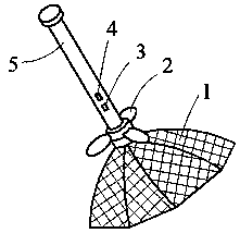
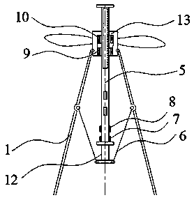
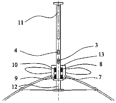
[0021] combine figure 1 , figure 2 and image 3 , an electric shock type mosquito and fly cover, including an umbrella-shaped electric shock cover 1, a soft leaf fan 2, an electric shock switch 3, a fan switch 4, a handle 5, an umbrella rib 6, a fixing sleeve 12, an electric shock conductive ring 7, and a fan conductive ring 8 , electric shock annular conduction groove 9, fan annular conduction groove 10, insulating protective cover 13 and accumulator 11.

[0022] The handle 5 is provided with an electric shock switch 3, a fan switch 4, a fixed sleeve 12, an electric shock conductive ring 7, a fan conductive ring 8, an electric shock annular conductive groove 9, a fan annular conductive groove 10, and an electric storage device 11. The electric storage device 11 is located at the top of the handle 5 , the fixed sleeve 12 is fixedly connected to the bottom...


PUM


Abstract

The invention discloses an electric shock type mosquito and fly capturing hood.A power storage device is located on the top of a handle, a fixing sleeve is located at the bottom of the handle, an electric shock conducting ring is located on the top of the fixing sleeve, and a fan conducting ring, an electric shock annular conducting groove, an electric shock switch, a fan switch and a fan annular conducting groove are sequentially arranged above the electric shock conducting ring from bottom to top; an insulation protection cover is located on the outer walls of the electric shock annular conducting groove and the fan annular conducting groove, the portion, located on the outer wall of the electric shock annular conducting groove, of the insulation protection cover is rotationally connected with one end of an umbrella-shaped electric shock hood body, the other end of the umbrella-shaped electric shock hood body and the fixing sleeve are located on the same side, multiple umbrella ribs are annularly distributed on the inner wall of the umbrella-shaped electric shock hood body, one end of each umbrella rib is rotationally connected with the umbrella-shaped electric shock hood body, and the other end of the umbrella rib is rotationally connected with the fixing sleeve; a soft-blade fan is arranged on the portion, located on the outer wall of the fan annular conducting groove, of the insulation protection cover.According to the electric shock type mosquito and fly capturing hood, the umbrella-shaped electric shock hood body is adopted and matched with an active capturing mode, the capturing area is large, the capturing probability is high, the power-on time of the umbrella-shaped electric shock hood body is controlled through the electric shock switch, and an unconscious electric shock is effectively prevented.

Description

technical field [0001] The invention relates to an insect extermination appliance, in particular to an electric shock type mosquito and fly trap. Background technique [0002] In daily life, in order to prevent the spread of diseases and maintain hygiene, people use various methods to kill mosquitoes and flies. At present, the methods of killing mosquitoes and flies mainly use fly paper, fly swatters, electric mosquito swatters, electric screens, pesticides, sprays, etc. Fly papers are passively eliminated and cannot actively attack mosquitoes; electric mosquito swatters or fly swatters The surface area of ​​the swatter is small, and there will be changes in the micro-airflow when it is waved. Mosquitoes and flies are very alert. Once they notice the change in the micro-airflow, they will fly away, and it is not easy to hit mosquitoes and flies; and kill mosquitoes and flies through pesticides and sprays. , will cause adverse effects on the human body and the environment. ...

Claims


Application Information

Patent Timeline
Patent Type & Authority Patents(China)
IPC IPC(8): A01M3/00A01M3/02
CPCA01M3/002A01M3/025
Inventor 赖信
Owner 赖信
Why Eureka
Try Eureka