
Environment-friendly and energy-saving indoor air purification treatment equipment

A technology for indoor air purification treatment, which is applied in the field of indoor air purification treatment equipment, can solve the problems such as the decline in the ventilation efficiency of filter elements, and achieve the effects of simple structure, reduced energy consumption, and reduced number of installations

Inactive Publication Date: 2022-03-01
陈珍妮
View PDF0 Cites 0 Cited by
  • Summary
  • Abstract
  • Description
  • Claims
  • Application Information

AI Technical Summary

Problems solved by technology

[0003] We have found in actual operation that because the inner wall of the filter element has a filter screen that intercepts coarse particles, and because the particle content is relatively large, the innermost filter screen of the filter element is usually the first to be dirty. Quickly dirty, resulting in a sharp decline in the ventilation efficiency of the entire filter element

Method used


Image

  • Environment-friendly and energy-saving indoor air purification treatment equipment
  • Environment-friendly and energy-saving indoor air purification treatment equipment
  • Environment-friendly and energy-saving indoor air purification treatment equipment

Examples


Embodiment 1

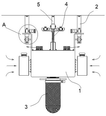
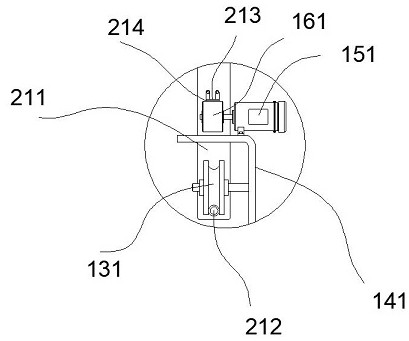
[0052] An environment-friendly and energy-saving indoor air purification treatment equipment, comprising a purifier 1 suspended inside a building, and sliding guide devices 2 installed on the inner bottom of the roof and located on both sides of the purifier 1, the The purifier 1 slides along the longitudinal direction of the sliding guide device 2; a cylindrical filter element 6 is built in the interior of the purifier 1, and a dust collection device for collecting coarse particles is installed at the bottom of the purifier 1 3. The upper part of the purifier 1 is provided with a cleaning structure 4, the cleaning structure 4 acts on the inner wall of the filter element 6, and sweeps the coarse particles attached to the inner wall of the filter element 6 downward to the dust collecting device 3 Inside; a guide plate 5 is installed at the bottom of the roof, and the cleaning mechanism 4 and the guide plate 5 are rollingly matched. Under the action of the guide plate 5, the clea...

Embodiment 2

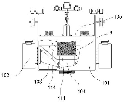
[0054] The purifier 1 includes a box body 101, the left and right sides of the box body 101 are provided with air inlet holes, and an air inlet fan 102 is installed at the air inlet hole, and the air inlet end of the air inlet fan 102 passes through the air inlet hole. After the air inlet hole is inserted into the box body 101, this end is connected with an air pipe 103; a connecting pipe 104 is installed at the inner axis of the box body 101, and the air pipe 103 communicates with the connecting pipe 104 The lower end of the air duct 103 extends downwards to the outside of the box 101, and the dust collecting device 3 is installed at the lower end of the air duct 103; the upper end of the box 101 is detachably installed with a cover plate 105 , the bottom of the cover plate 105 is provided with a convex tube 106 corresponding to the connecting pipe 104, and the top of the cover plate 105 is provided with an air outlet cover 114; the outer wall of the connecting pipe 104 is pro...

Embodiment 3

[0058] The dust collecting device 3 includes a ring body 301 threadedly connected with the connecting pipe 104 , a plurality of handles 302 are arranged on the outer wall of the ring body 301 , and a dust bag 303 is installed at the bottom of the ring body 301 .

[0059] The dust collecting device 3 is detachable by screw.


PUM


Abstract

The invention discloses environment-friendly and energy-saving indoor air purification treatment equipment which comprises a purifier arranged in a building in a suspended mode and sliding guide devices installed at the bottom in a roof and located on the two sides of the purifier, and the purifier slides in the longitudinal direction of the sliding guide devices. A cylindrical filter element is arranged in the purifier, a dust collecting device for collecting coarse particles is installed at the bottom of the purifier, a cleaning structure is arranged on the upper portion of the purifier, and the cleaning structure acts on the inner wall of the filter element and sweeps the coarse particles attached to the inner wall of the filter element downwards into the dust collecting device. The device can be used for cleaning the inner-layer filter screen of the filter element during operation.

Description

technical field [0001] The invention relates to an environment-friendly and energy-saving indoor air purification treatment equipment. Background technique [0002] In the production workshop, especially the production workshop with a large amount of dust such as stone, wood, textile, etc., the air inside needs to be continuously purified. The traditional treatment method is to use multiple purifiers to operate in the workshop. A cylindrical filter element is installed inside, and the air is sucked into the inner side of the filter element, and then penetrates from the inner side to the outer side of the filter element and is filtered. [0003] We have found in actual operation that because the inner wall of the filter element has a filter screen that intercepts coarse particles, and because the particle content is relatively large, the innermost filter screen of the filter element is usually the first to be dirty. Rapid dirt, resulting in a sharp decline in the ventilation...

Claims


Application Information

Patent Timeline
Patent Type & Authority Applications(China)
IPC IPC(8): F24F8/108F24F8/90F24F13/28F24F13/32
CPCF24F8/108F24F8/90F24F13/28F24F13/32
Inventor 陈珍妮沈斌
Owner 陈珍妮
Learn More