[0056]The technical solutions in the embodiments of the present invention will be clearly and completely described below in conjunction with the accompanying drawings in the embodiments of the present invention. Obviously, the described embodiments are only a part of the embodiments of the present invention, rather than all the embodiments. Based on the embodiments of the present invention, all other embodiments obtained by those of ordinary skill in the art without creative work shall fall within the protection scope of the present invention.
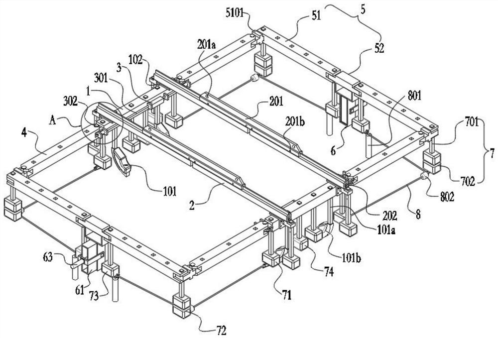
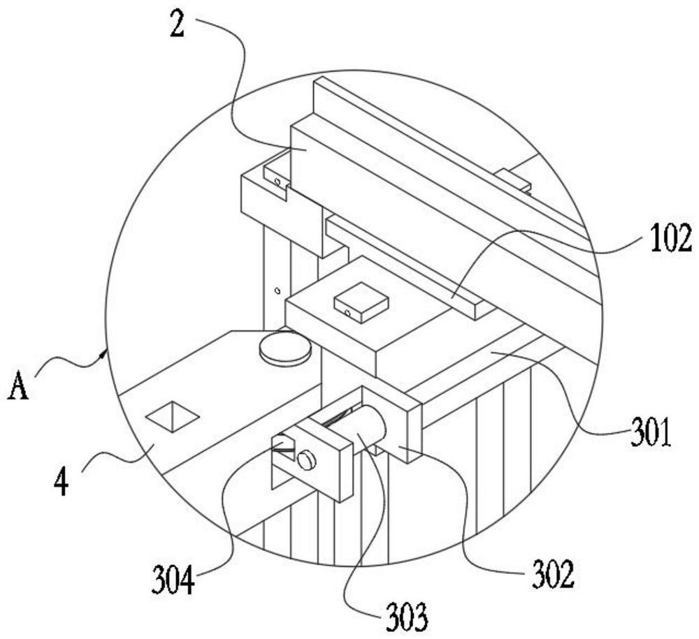
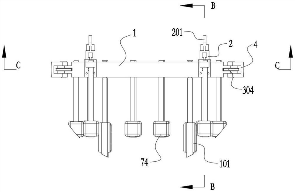
[0057]SeeFigure 1-13 , The present invention provides a technical solution: an underwater robot area salvage and capture device for marine engineering exploration, including:
[0058]Two central fixed beams 1 arranged in parallel and with variable spacing, and the tops of the two central fixed beams 1 are slidingly connected to two positioning hoisting slide rails 2 arranged in parallel with fixed spacing, such asFigure 1-4Specifically: positioning and hoisting guide blocks 102 are fixedly installed on the tops of both sides of the central fixed beam 1, and the positioning and hoisting guide blocks 102 are slidably clamped with the guide grooves 202 provided at the bottom of the positioning and hoisting slide rails 2, and the positioning and hoisting guide blocks 102 and guides The groove 202 is a matched T-shaped structure.
[0059]A positioning hoisting arm 201 is fixedly installed on the top of the positioning hoisting slide rail 2, and the top of the positioning hoisting slide rail 2 is fixedly connected to the positioning hoisting arm 201 through a pin 201b. The positioning hoisting arm 201 is provided with a plurality of hoisting holes 201a, which are in the hoisting holes 201a. The wire rope for lifting is fixedly connected to facilitate the mother ship to lift or lower the salvage and capture device.
[0060]Both ends of the two middle fixed beams 1 are fixedly installed with an inflatable conformable air cushion 101 extending downwards. The inflatable conformable air cushion 101 is composed of a support rod 101a and a conformable air cushion vertically installed on the middle fixed beam 1 The conformable air cushion 101b is fixed to the bottom of the support rod 101a, and the conformable air cushion 101b is inflated by an external air pump. When the autonomous underwater vehicle is positioned axially, the conformable air cushion 101b is inflated by the external air pump, so that the conformable air cushion 101b is inflated. 101b is squeezed on the side of the autonomous underwater vehicle to achieve complete positioning of the autonomous underwater vehicle and complete the capture process.
[0061]A dual-axis hydraulic motor 3 is installed on the inner side of the two positioning and hoisting slide rails 2, and the two drive shafts 301 of the hydraulic motor 3 extend to both sides, and the ends of the two drive shafts 301 are fixedly connected to a worm 303 and a worm 303. Rotatingly mounted on the end block 302 provided at the end of the positioning and hoisting slide rail 2. At the same time, the end block 302 is also rotated and installed with a worm wheel 304 that meshes with the worm 303. The worm wheel 304 is connected to the movable end of the positioning and hoisting slide rail 2. One end of the beam 4 is fixedly connected;
[0062]The other end of the movable cross beam 4 is rotatably connected to the end of the end beam 5 through the movable sub-section 5101. The number of the end beams 5 is two, which are arranged parallel to each other on the outside of the two positioning and hoisting slide rails 2, and the two ends The beam 5 is kept parallel to the two positioning and hoisting slide rails 2.
[0063]The end beam 5 is composed of two end fixed cross beams 51 and a fixed short section 52 fixedly connected between the two end fixed cross beams 51. The two end fixed cross beams 51 and the fixed short section 52 are located on the same straight line, The outer ends of the two end fixed cross beams 51 are both fixedly connected with a movable sub section 5101, and the movable sub section 5101 is rotatably connected with the movable cross beam 4.
[0064]The middle of the two end beams 5 are hoisted downwards with an end limit assembly 6 which includes a limit slider 62 that can be clamped on the end of the autonomous underwater vehicle, and a fixed installation on the The slide frame 61 at the bottom of the fixed short section 52 and the hydraulic cylinder 63 fixedly installed on the outside of the slide frame 61, the limit slider 62 is slidably arranged in the slide frame 61, and the outer end of the limit slider 62 is connected to the hydraulic cylinder The driving end of 63 is fixedly connected, and the inner end of the limit sliding block 62 is fixedly connected to a rubber protection pad.
[0065]Both ends of the central fixed beam 1 are movably inserted into a first float 71 extending downward, and both ends of the end beam 5 are movably inserted into a second float 72 extending downward. The end beam 5 Two third floats 73 extending downward are movably inserted in the middle of the, wherein the third float 73 is movably inserted on the end of the movable beam 4 on the side close to the fixed sub-section 52.
[0066]The bottom of the first float 71 is fixedly installed with a first closed ring 7101, the bottom of the second float 72 is fixedly installed with a top open split ring 7201, the bottom of the third float 73 is fixedly installed with a second closed ring 7301, and one end of the limit cable 8 is connected with The first closed ring 7101 is fixed, the limit cable 8 moves around the split ring 7201, and then passes through the second closed ring 7301. A float 802 is fixedly installed on the limit cable 8 near the split ring 7201. The other end is fixedly connected with a vertical downward counterweight 801, and the counterweight 801 is located under the second closed loop 7301.
[0067]A plurality of supporting floats 74 extending downward are movably inserted in the middle of the middle fixed beam 1.
[0068]The first float 71, the second float 72, the third float 73 and the support float 74 are all composed of a float assembly 7. The float assembly 7 includes a vertically installed limit rod 701 and a limit fixedly installed at the bottom of the limit rod 701 Float 702, the two ends of the end beam 5, the two ends and the middle of the end beam 5 are vertically penetrated with square holes that cooperate with the limit rod 701, and the top of the limit rod 701 is also provided with a stopper to limit its separation End caps with square holes.
[0069]An area salvage and capture method for underwater robots for marine engineering exploration, which adopts the aforementioned salvage and capture device, and specifically includes the following steps:
[0070]S1: When salvaging the autonomous underwater vehicle, first assemble the salvage and capture device, hang the middle of the limit cable 8 on the split ring 7201 under the second float 72 to increase the capture area, and then lift the salvage and capture device Go above the autonomous underwater vehicle, so that the autonomous underwater vehicle is within the capture range of the salvage and capture device;
[0071]S2: Put down the salvage and capture device to float on the water. While capturing the autonomous underwater vehicle, rely on the buoyancy of the float 802 on the limit cable 8 to make the limit cable 8 slide out of the split ring 7201, using counterweights The gravity of 801 stretches the limit cable 8 so that the limit cable 8 is flush with the water surface, which acts as a limit, and then continues to lower a section of wire rope, so that the wire rope used for lifting is in a relaxed state, so that the fishing catch device can avoid Interference of sea conditions on the mother ship;
[0072]S3: Use the two hydraulic motors 3 on the central fixed beam 1 to drive the transmission structure of the worm 303 and the turbine 304, and drive the four movable beams 4 to rotate, so that the two central fixed beams 1 are moved along under the action of the positioning and hoisting guide block 102. The positioning hoisting slide rail 2 is gradually retracted to position the autonomous underwater vehicle;
[0073]In this process, if the axis of the autonomous underwater vehicle is perpendicular to the central fixed beam 1 in the special situation, the autonomous underwater vehicle needs to be rotated to avoid this special situation;
[0074]S4: After the autonomous underwater vehicle is successfully limited in the radial direction, first use the hydraulic cylinder 63 to push the limit slider 62 to axially position the autonomous underwater vehicle, and then inflate the accompanying air cushion 101b on the support rod 101a to achieve Complete positioning of the autonomous underwater vehicle and complete the capture process;
[0075]S5: After the autonomous underwater vehicle is hoisted back to the mother ship, the autonomous underwater vehicle is hoisted on a V-shaped frame to release the salvage and capture device, and the work process is over.
[0076]Although the embodiments of the present invention have been shown and described, those of ordinary skill in the art can understand that various changes, modifications, and substitutions can be made to these embodiments without departing from the principle and spirit of the present invention. And variations, the scope of the present invention is defined by the appended claims and their equivalents.