Flexible transmission device, adjustable spring, energy storage component, robot and locking device

A technology of flexible transmission and energy storage components, which is applied in the field of robotics and can solve problems such as damage to components or workers

Active Publication Date: 2016-07-06
ROBOT TIME BEIJING TECH CO LTD
View PDF10 Cites 4 Cited by
  • Summary
  • Abstract
  • Description
  • Claims
  • Application Information

AI Technical Summary

Problems solved by technology

[0002] Existing robots and mechanical arms, etc., use rigid transmission. In the case of rigid transmission, if you encounter obstacles, especially when touching human limbs or products that need to be handled, due to the hardness of human limbs or the rigidity of products, When the resistance that can be caused is less than the driving force and the transmission capacity of the transmission device, the mechanical arm or robot will continue to move forward, which may cause damage to other components or workers

Method used


Image

  • Flexible transmission device, adjustable spring, energy storage component, robot and locking device
  • Flexible transmission device, adjustable spring, energy storage component, robot and locking device
  • Flexible transmission device, adjustable spring, energy storage component, robot and locking device

Examples


Embodiment 1

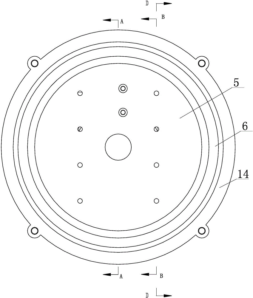
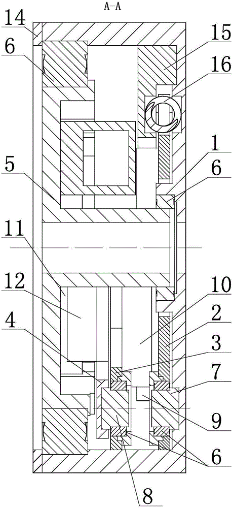
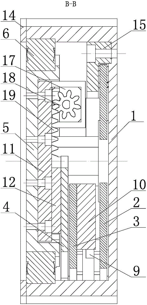
[0054] figure 1 It is the side view of the flexible transmission device of embodiment 1: figure 2 yes figure 1 A-A sectional view of ; image 3 yes figure 1 The B-B sectional view of; Figure 4 yes figure 1 D-D sectional view of ; Figure 5 It is a schematic diagram of the three-dimensional structure of the flexible driving device in embodiment 1 after the first end cover is removed; Figure 6 It is a side view of the schematic diagram of the mechanism of embodiment 1; Figure 7 It is the front view of the mechanism diagram of Embodiment 1.

[0055] In the figure, the meanings of each reference mark are as follows:

[0056] 1. First end cover; 2. First swing arm; 3. Second swing arm; 4. Third swing arm; 5. Second end cover; 6. Rolling bearing; 7. First shaft; 8. Second shaft ; 9, the first guide rail; 10, the first slider; 11, the second guide rail; 12, the second slider; 14, the pressure ring; 15, the first gland; 16, the compression spring; 17, the driving motor; 1...

Embodiment 2

[0080] Figure 8 It is a schematic diagram of embodiment 2 where the flexible transmission device is cut along the middle of the second shaft 8 and viewed in the direction of the first end cover 1 . In the figure, the definitions of the reference numerals of the first embodiment are still used for the same reference numerals used in the drawings of the first embodiment. In the figure, the meanings represented by the newly appearing reference numerals in the accompanying drawings with respect to embodiment 1 are as follows: 20, tension spring;

[0081] The difference between this embodiment and embodiment 1 is:

[0082] In Embodiment 1, a compression spring 16 is provided to provide anti-rotation torque for rigid transmission. In fact, a pair of extension springs can also be provided—a first extension spring and a second extension spring, the first extension spring has a first end and a second end, and the second extension spring has a third end and a second end. The fourth ...

Embodiment 3

[0085] Figure 9 It is a schematic diagram of the movement of the mechanism in Embodiment 3. In the figure, the same reference numerals as in the drawings used in Embodiment 1 still follow the definition of the reference numerals in Embodiment 1.

[0086] In this embodiment, the corresponding relationship between each relative movement member and specific parts is as follows: the first relative movement member is the first end cap 1, the second relative movement member is the second end cap 5, and the third relative movement member is the third rocker. arm, the fourth relative movement member is the second rocker arm, the fifth relative movement member is the first rocker arm,

[0087] The difference between this embodiment and Embodiment 1 is that in Embodiment 1, the driving motor 17 is installed on the second end cover 5, and the rack 19 meshing with the output gear 18 at the output end of the driving motor 17 is arranged on the third rocker. arm, and in this embodiment, t...


PUM


Abstract

The invention relates to a flexible transmission device and a robot provided with the flexible transmission device. The flexible transmission device comprises a driving component, a first relative movement component, a second relative movement component, a third relative movement component, a fourth relative movement component and a fifth relative movement component; the first relative movement component and the second relative movement component are arranged in a manner of being capable of freely and relatively rotating along a first rotation axis; the third relative movement component and the fourth relative movement component are arranged in a manner of being capable of freely and relatively rotating along a second rotation axis; the first relative movement component and the fifth relative movement component are arranged in a manner of being capable of freely and relatively rotating along a third rotation axis; the second relative movement component and the third relative movement component are in sliding connection; and the fourth relative movement component and the fifth relative movement component are in sliding connection. The flexible transmission device can be freely switched between the flexible rotation state and the rigid transmission state.

Description

technical field [0001] The invention belongs to transmission device technology. In particular, it relates to a flexible transmission device, an adjustable spring, an energy storage component and a locking component, and a robot using the flexible transmission device. Background technique [0002] Existing robots and mechanical arms, etc., use rigid transmission. In the case of rigid transmission, if you encounter obstacles, especially when touching human limbs or products that need to be handled, due to the hardness of human limbs or the rigidity of products, When the resistance that can be caused is less than the driving force and the transmission capacity of the transmission device, the mechanical arm or robot will continue to move forward, which may cause damage to other components or workers. Contents of the invention [0003] In order to overcome the technical problems in the prior art, the present invention provides a flexible transmission device, an adjustable spri...

Claims


Application Information

Patent Timeline
Patent Type & Authority Applications(China)
IPC IPC(8): B25J9/08B25J19/06
CPCB25J9/08B25J19/06
Inventor 郑世杰
Owner ROBOT TIME BEIJING TECH CO LTD
Why Eureka
Try Eureka