
Floating upright post protective net structure

A technology for protective nets and columns, applied in the field of protective nets, can solve the problems of limited practical effect of protective columns, consumption of rockfall kinetic energy, and failure of fixed columns to buffer, etc., to achieve good rockfall impact resistance, improve adaptability, and avoid damage.

Inactive Publication Date: 2016-07-06
CHINA RAILWAY ERYUAN ENG GRP CO LTD
View PDF4 Cites 0 Cited by
  • Summary
  • Abstract
  • Description
  • Claims
  • Application Information

AI Technical Summary

Problems solved by technology

The structure of the fixed column structure protective net is simple and convenient for construction. The disadvantage is that if the falling rock directly hits the fixed column, the fixed column cannot buffer and consume the kinetic energy of the falling rock through retreat, and it will be directly damaged by the falling rock, and the entire protective net will lose its protective function.
Although certain foot chains and other devices are installed at the bottom of some fixed columns to buffer the falling rocks by tilting at a certain angle when falling rocks hit the fixed columns, the actual effect of protecting the columns is limited, and it cannot buffer large and medium-sized rockfalls.
In addition, the fixed column is often fixed by driving into the ground to a certain depth. Therefore, there are certain requirements for the soil quality along the protective net. When the soil is loose or hard, it is often necessary to adopt corresponding engineering for the stratum foundation at the position of the column. This will undoubtedly increase the construction cost of the protective net project

Method used


Image

  • Floating upright post protective net structure
  • Floating upright post protective net structure
  • Floating upright post protective net structure

Examples


Embodiment Construction

[0013] The present invention will be further described below in conjunction with the accompanying drawings and embodiments.

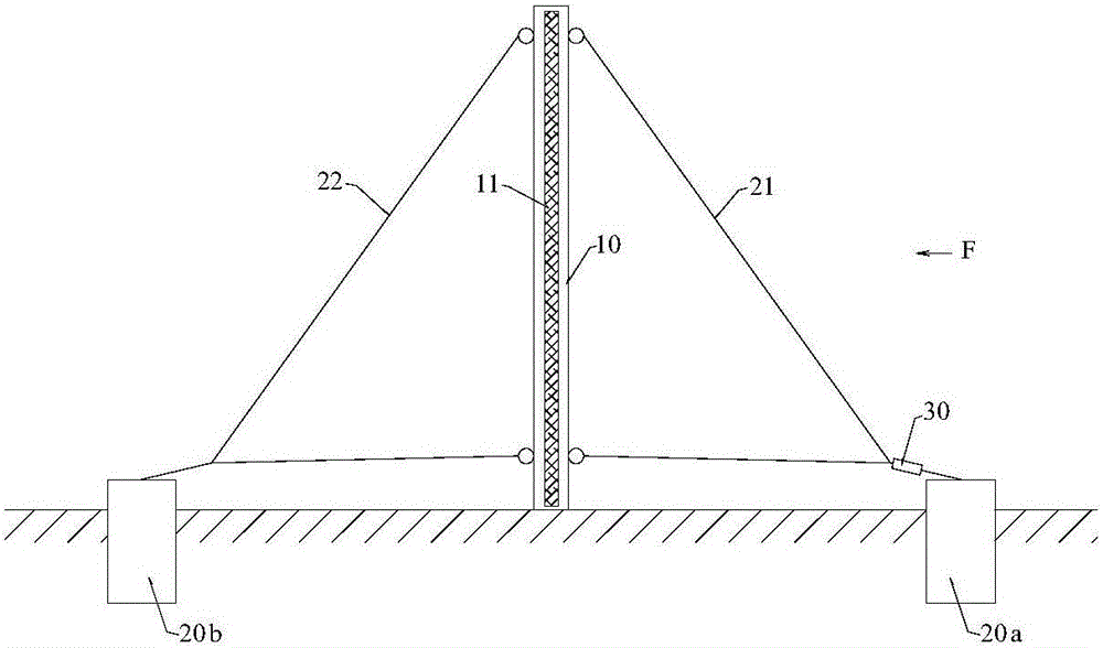
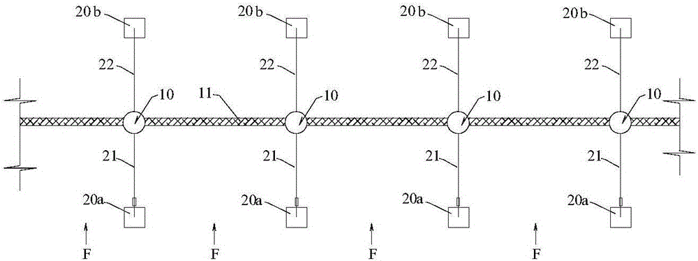
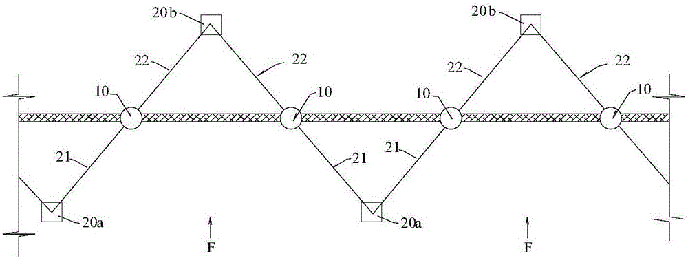
[0014] In this specification, in order to accurately describe and avoid ambiguity, the side of the column 10 and the protective net surface 11 facing the rockfall impact direction F is defined as the "front side", such as "front side anchoring member 20a", "front side steel The other side is defined as the "rear side", such as "rear side anchoring member 20b", "rear side steel cable 22" and so on.

[0015] refer to figure 1 with figure 2 , the structure of the floating column protective net of the present invention includes columns 10 arranged in rows and a protective net body 11 suspended and fixed thereon. A front anchoring member 20a and a rear anchoring member 20b integrally connected with the ground are arranged on both sides of the column 10 . Each column 10 is suspended above the ground by a pair of front side steel cables 21 and rear side st...


PUM


Abstract

The invention discloses a floating upright post protective net structure and aims to prevent upright posts from being damaged by direct impact of falling rocks. The floating upright post protective net structure comprises the upright posts which are arranged in rows, and a protective net body which is fixed to the upright posts; a front side anchoring component and a rear side anchoring component which are integrally connected with the stratum are respectively arranged on the two sides of each upright post. Each upright post is suspended above the ground through a pair of front side steel rope and rear side steel rope; each front side steel rope is fixedly connected at three points among the upper part of the corresponding upright post, the corresponding front side anchoring component and the lower part of the corresponding upright post and is tensioned; each rear side steel rope is fixedly connected to three points among the upper part of the corresponding upright post, the corresponding rear side anchoring component and the lower part of the corresponding upright post and is tensioned. At least one damper is arranged on each front side steel rope.

Description

technical field [0001] The invention relates to a protective net, in particular to an installation and fixing structure of a protective net and a column. Background technique [0002] In order to prevent the unstable mountain and falling rocks from causing serious harm to people, vehicles, buildings, etc., various protective nets act as "safety guards" for the safety of life and property in modern society. [0003] Common protective nets are mainly composed of fixed columns and steel cable mesh surfaces of different structures. In order to improve the protection capacity, buffer devices such as dampers are often installed. The fixed column is the backbone of the protective net, which is directly fixed to the ground, and its main function is to stabilize and erect the steel cable net surface. The fixed column structure protective net has a simple structure and is convenient for construction. The disadvantage is that if the falling rock directly hits the fixed column, the fix...

Claims


Application Information

Patent Timeline
IPC IPC(8): E01F7/04
CPCE01F7/045
Inventor 袁志刚李晓园王珣郑小艳杨吉忠吴件
Owner CHINA RAILWAY ERYUAN ENG GRP CO LTD
Learn More