Connecting structure for floor drain core and floor drain body

A technology for connecting structures and cores, applied in drainage structures, waterway systems, water supply devices, etc., can solve the problems of small force range, troublesome operation, easy to break the core 2', etc., to simplify the slot structure and save manpower Cost and effect of simplifying the machining process

Active Publication Date: 2016-07-06
张金荣
View PDF5 Cites 0 Cited by
  • Summary
  • Abstract
  • Description
  • Claims
  • Application Information

AI Technical Summary

Problems solved by technology

But at present, for the convenience of disassembly and assembly, the water inlet 23' of the core 2' is generally provided with a "one"-shaped or "S"-shaped bar 24', wherein the "one"-shaped structure like figure 2 As shown, when disassembling, two fingers are inserted into the water inlet to grasp the horizontal bar 24' to rotate the core 2', not only the range of force is small, but the operation is troublesome. In the middle part, the torque is very small when turning. When the floor drain is stuck tightly after long-term use, it is difficult to turn the core 2', which

Method used


Image

  • Connecting structure for floor drain core and floor drain body
  • Connecting structure for floor drain core and floor drain body
  • Connecting structure for floor drain core and floor drain body

Examples


Embodiment Construction

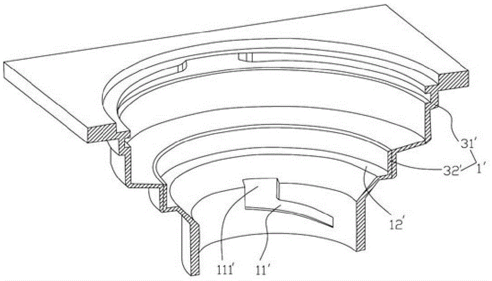
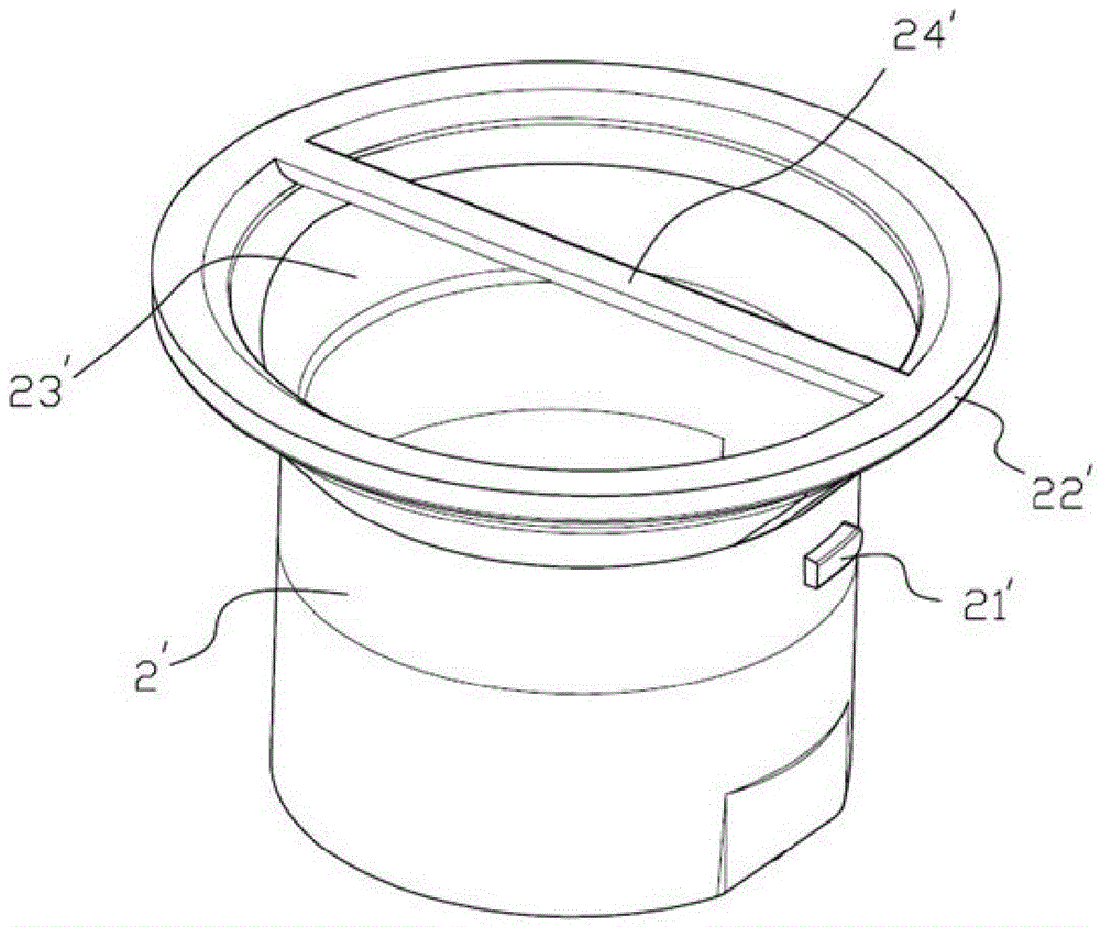
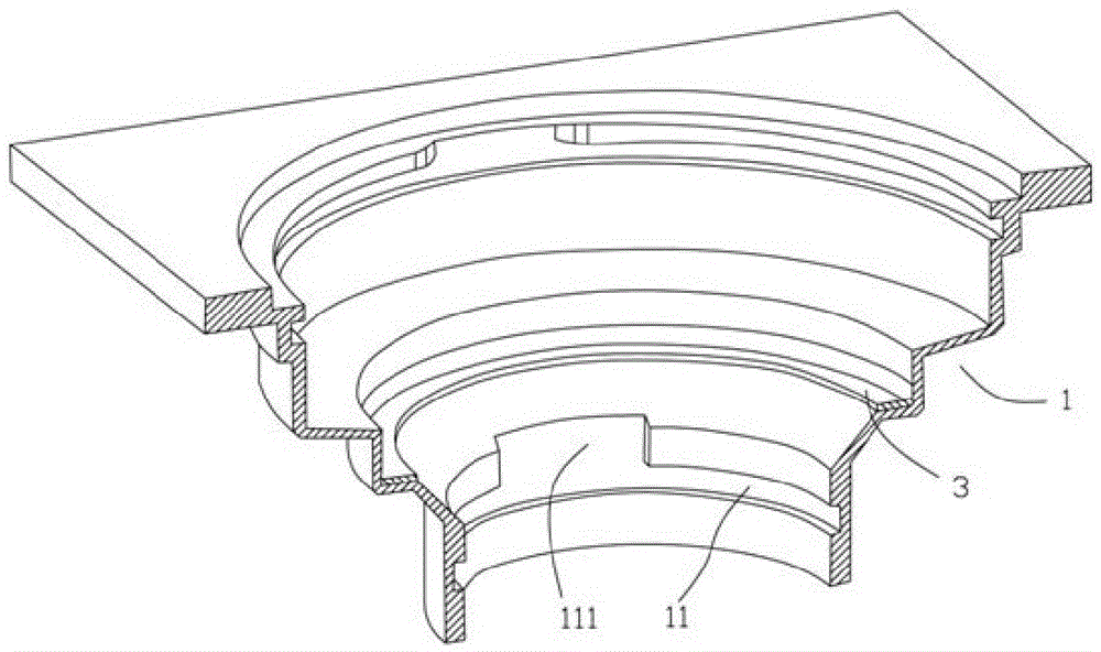
[0027] Such as image 3 with 4 As shown, a connection structure between the floor drain core and the body, including the floor drain body 1 and the core 2, the inner wall of the floor drain body 1 is provided with a card slot 11, and the outer wall of the core 2 is provided with several protrusions that can be engaged with the card slot 11. Block 21.

[0028] The clamping groove 11 is an annular groove of equal depth, and an upper notch 111 is provided above the annular groove at a position corresponding to each core protrusion 21 . When the annular groove structure of the card groove 11 is connected with the bump 21, it can be assembled in two directions. As long as the bump 21 is correspondingly snapped into the corresponding upper notch 111, the bump 21 can be snapped into it by turning counterclockwise or clockwise. The snap connection between the core 2 and the body 1 is realized in the annular groove. Even if debris enters the guide groove 11 in actual use and makes on...


PUM


Abstract

The invention discloses a connecting structure for a floor drain core and a floor drain body. The connecting structure comprises the floor drain body and the core; the inner wall of the floor drain body is provided with a clamping groove, the outer wall of the core is provided with a plurality of convex blocks which can be connected with the clamping groove in a clamped mode, an isobathic annular groove is adopted as the clamping groove, and upper notches are formed in the positions, corresponding to the convex blocks of the core, of the upper portion of the annular groove; the height of the two ends of each convex block is smaller than that of the middle of the convex block. The connecting structure for the floor drain core and the floor drain body has the advantages that disassembly and assembly are convenient, no influence can be caused to water entry of the floor drain core, and the structure is simple and practical.

Description

technical field [0001] The invention relates to a floor drain, in particular to a connection structure between a floor drain core and a body. Background technique [0002] The floor drain is generally composed of a floor drain body, an anti-odor and insect-proof core and a cover plate. The floor drain body is mostly made of metal, while the floor drain core is made of plastic material, and is realized by the protrusion on the outer wall of the floor drain core and the card slot on the inner wall of the floor drain body. Snap connection. [0003] Here, if figure 1 with 2 As shown, the grooves on the inner wall of the floor drain body 1' above are several guide grooves 11' evenly distributed in the circumferential direction, and each guide groove 11' is provided with a notch 111' where the core 2' bump 21' snaps in. The bottom of the guide groove 11' extends obliquely downward along the inner wall of the floor drain body 1' and its depth is continuously increased. When ass...

Claims


Application Information

Patent Timeline
IPC IPC(8): E03F5/04
CPCE03F5/0407
Inventor 张金荣
Owner 张金荣
Why Eureka
Try Eureka