

A mobile terminal projection method, terminal equipment and system
A mobile terminal and terminal equipment technology, applied in the field of communication, can solve problems such as affecting user experience, reduce location dependence, and achieve the effect of resource sharing
- Summary
- Abstract
- Description
- Claims
- Application Information
AI Technical Summary
Problems solved by technology
Method used
Image

Examples
Embodiment 1
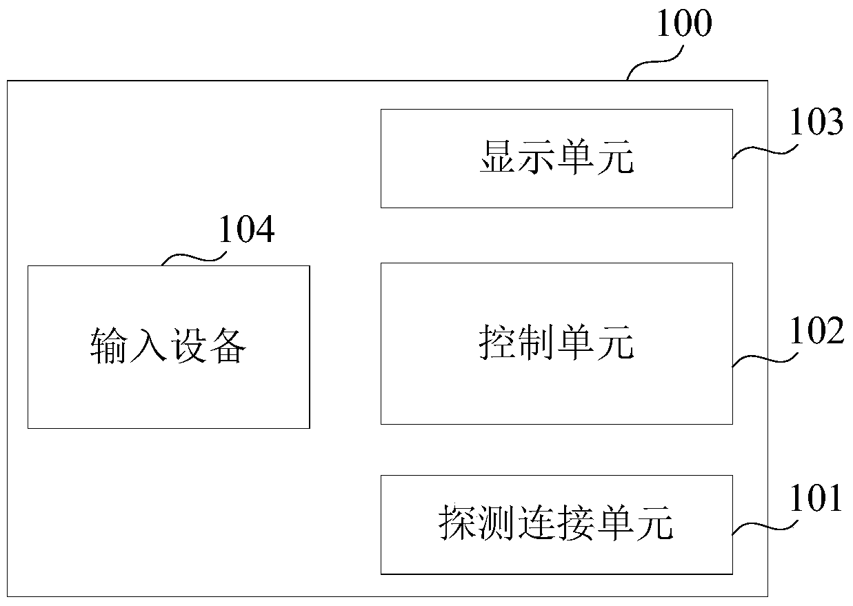
[0063] see figure 1 , is a schematic diagram of a hardware structure of a terminal device according to an embodiment of the present invention.
[0064] The terminal device 100 in this embodiment of the present invention includes: a detection connection unit 101 , a control unit 102 , and a display unit 103 .
[0065] When the terminal device 100 is used as the projection side (Source end):
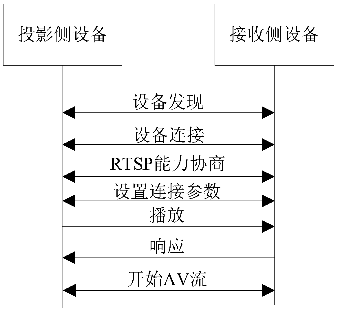
[0066] The detection connection unit 101 is used for performing device discovery to search for other adjacent devices available with Wi-Fi Display service. When other devices are discovered, the detection connection unit 101 interacts with other devices and negotiates capabilities through the RTSP protocol, so that the device 100 is connected to other devices.
[0067] The control unit 102 controls basic operations within the terminal device 100 . Specifically, the control unit 102 controls so that the content (screen data) displayed by the display unit 103 is sent to other devices thro...
Embodiment 2
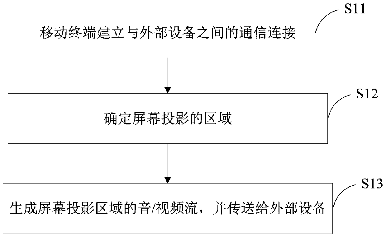
[0075] Based on the hardware structure of the above-mentioned terminal equipment and the search process of the terminal on the projection side, a projection method for split-screen equipment of the present invention is proposed. Such as image 3 As shown, in the embodiment of the present invention, the projection method of the split screen of the device is applied to the mobile terminal, including steps:
[0076] S11, the mobile terminal establishes a communication connection with an external device.
[0077] It should be understood that a mobile terminal is equivalent to a projection side device, such as a mobile phone, a PAD (tablet computer), etc., and an external device is equivalent to a receiving side device, and the external device includes a display screen or a screen, such as a mobile phone, a TV, a projector, etc. Under certain conditions, the mobile terminal can be converted into an external device, that is, a receiving-side device, and the external device can be c...
Embodiment 3
[0088] Based on the above embodiments, the present invention also proposes a multi-screen projection method, in which there are one or more receiving-side devices relative to one projection-side device. see Figure 5 It is a schematic diagram of a network structure capable of realizing multi-screen projection control according to an embodiment of the present invention.
[0089] The network 1000 includes: one projection side device 200 and at least one reception side device 300 . The hardware structure of the projection side device 200 and the receiving side device 300 can refer to the above-mentioned figure 1 shown.
[0090] The network 1000 has the same meaning as a Wi-Fi peer-to-peer (P2P) network. The projection-side device and the reception-side device in the network 1000 are directly connected to each other by Wi-Fi direct without using a wireless local area network (WLAN) access point (AP) or the like.
[0091]Specifically, the projection-side device 200 performs dev...
PUM
 Abstract
Description
Claims
Application Information