

Depositing and withdrawing device, dynamic correction sensor thereof, correction method and device
A dynamic correction and sensor technology, applied in the field of sensor detection, can solve the problems of limited linear range of sensors, limited adjustment levels, frequent manual intervention, etc.
- Summary
- Abstract
- Description
- Claims
- Application Information
AI Technical Summary
Problems solved by technology
Method used
Image

Examples
Embodiment 1
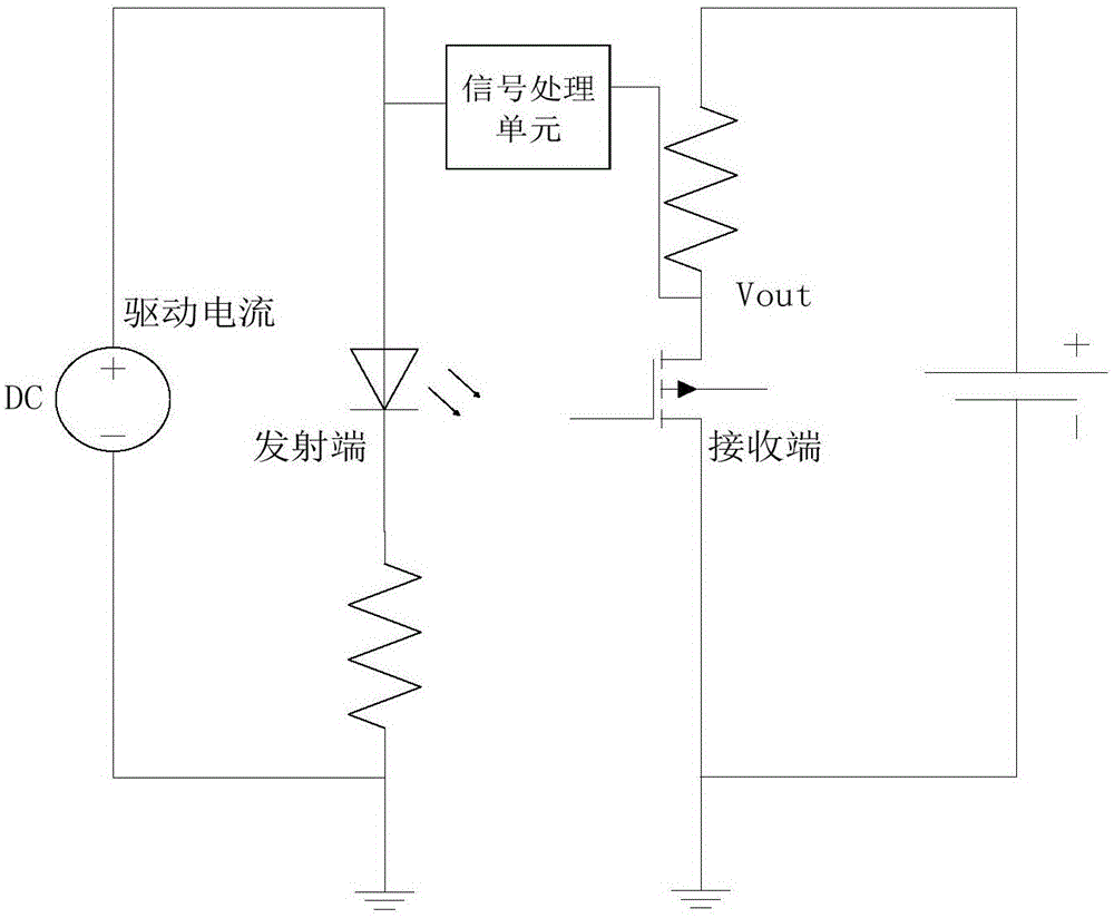
[0032] One of the specific embodiments of the present invention, this embodiment provides a deposit and withdrawal device with low maintenance cost, the deposit and withdrawal device includes a sensor for judging whether there is a banknote passing through the banknote channel, the storage device adopts a dynamic correction Functional sensor to judge whether there is a banknote passing through the banknote channel, the structure of the sensor with dynamic correction function is as follows: figure 1 As shown, it includes a transmitting end, a receiving end and a signal processing unit. The transmitting end and the receiving end are arranged opposite to each other. The receiving end receives the light emitted by the transmitting end and generates a sampling value. In this embodiment, the larger the sampling value, the greater the sampling value. It means that the less light collected by the receiving end.
[0033] The signal processing unit compares the sampling value of the rec...
Embodiment 2
[0045] The second specific embodiment of the present invention, the main technical solution of this embodiment is the same as that of Embodiment 1, and the features not explained in this embodiment are explained in Embodiment 1, and will not be repeated here. The difference between this embodiment and Embodiment 1 is that the transmitting end and the receiving end are set in the same direction, the light emitted by the transmitting end returns to the receiving end after being reflected, and the signal processing unit compares the sampling value of the receiving end with the threshold value V_T, if the sampling value is less than The threshold V_T indicates that the transmitting end of the sensor is blocked (there is a reflector), that is, there is an approaching object on the facing side of the sensor. The dynamic correction scheme for this type of sensor is consistent with Embodiment 1.
Embodiment 3
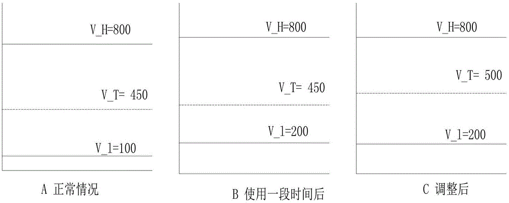
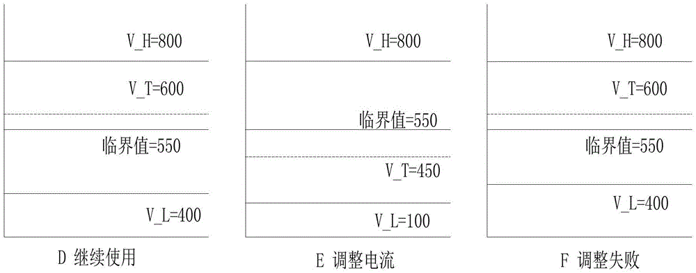
[0047] This embodiment provides a sensor dynamic correction method. The sensor to which this method is applied includes a transmitter and a receiver. The receiver receives the light emitted by the transmitter and generates a sample value, and compares the sample value of the receiver with a threshold to determine the Whether the receiving end is blocked, the implementation process of the sensor dynamic correction method is as follows Figure 5 As shown, the details are as follows:
[0048] In step A, the threshold is automatically corrected according to the sampling value V_L when the receiving end is not blocked, so that the variation trend of the threshold is consistent with the variation trend of the sampling value when the receiving end is not blocked.
[0049] Specifically, in step A, the step of automatically correcting the threshold according to the sampling value V_L when the receiving end is not blocked is specifically: superimposing the sampling value V_L when the re...
PUM
 Abstract
Description
Claims
Application Information