Mobile robot system and autonomous charging method thereof

A mobile robot and autonomous charging technology, which is applied in the direction of data exchange chargers, manipulators, collectors, etc., can solve problems such as limited, misplaced, and positional alignment problems

Inactive Publication Date: 2016-07-06
SHANGHAI SLAMTEC
View PDF4 Cites 21 Cited by
  • Summary
  • Abstract
  • Description
  • Claims
  • Application Information

AI Technical Summary

Problems solved by technology

The bottom-mounted contact charging requires a high distance between the chassis of the mobile robot and the ground. If the distance from the ground is too close, the obstacles that the robot can cross are very limited; if the distance from the ground is too high, the charging contact on the charging pile will be difficult. Touching and reliably connecting to contact contacts on the robot can have a big impact on the design
For side contact charging, the contact points of the robot and the contact points of the charging pile are very close to each other. When the robot is docked, it is easy to cause misalignment, resulting in poor charging efficiency.
[0004] In addition, existing mobile robots also face very serious safety issues when charging
For example, since the position of the charging contact on the robot is fixed, the charging contact itself needs to be exposed all the time, which is prone to wear, oxidation, poor contact, etc.
Moreover, there will be obvious safety hazards in the use of exposed charging contacts
Furthermore, the contact area between the existing charging contacts and the contact contacts on the charging pile is not very large, and it is easy to cause alignment problems, which will have a greater disadvantage to the charging efficiency during high-power charging. influences

Method used


Image

  • Mobile robot system and autonomous charging method thereof
  • Mobile robot system and autonomous charging method thereof
  • Mobile robot system and autonomous charging method thereof

Examples


Embodiment Construction

[0039]In order to make the technical content disclosed in this application more detailed and complete, reference may be made to the drawings and the following various specific embodiments of the present invention, and the same symbols in the drawings represent the same or similar components. However, those skilled in the art should understand that the examples provided below are not intended to limit the scope of the present invention. In addition, the drawings are only for schematic illustration and are not drawn according to their original scale.

[0040] The specific implementation manners of various aspects of the present invention will be further described in detail below with reference to the accompanying drawings.

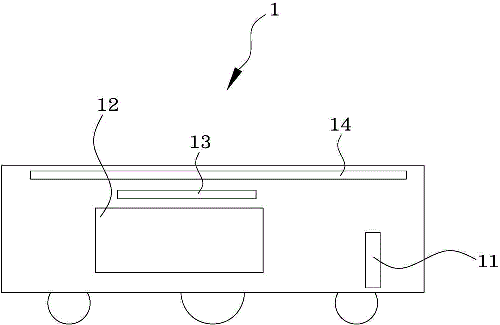
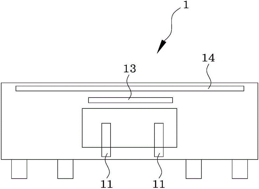
[0041] Figure 1A According to an embodiment of the present invention, a schematic structural diagram of a robot body in an autonomously rechargeable mobile robot system is shown, Figure 1B show Figure 1A Another view of the robot body.

[0042] As menti...


PUM


Abstract

The invention provides a mobile robot system and an autonomous charging method thereof. The mobile robot system comprises a robot body and a charging adapter. The robot body comprises a charging contact point, an energy storage module and a master control module. The charging contact point is configured to be able to extend to the exterior of the body or retract to the interior of the body. The energy storage module is used for providing a cruising capability for normal operation of the body. The master control module is connected with the energy storage module. The charging adapter comprises a sensing recognition module and a branch control module. The branch control module communicates with the master control module. When the robot body is in a charging state, the charging contact point extends to the exterior of the body and contacts the charging adapter. When the robot body stops charging, the charging contact point retracts to the interior of the body. Compared with the prior art, the charging point of the robot body is configured to be telescopic and is avoided to be exposed outside all the time, and abrasion, oxidation, poor contact and the like are reduced.

Description

technical field [0001] The invention relates to a charging technology for a mobile robot, in particular to a mobile robot and a mobile robot system for autonomously charging the mobile robot. Background technique [0002] With the rapid development of sensor, intelligent control and energy technologies, more and more service robots have been gradually used in different service occasions. Since people hope that service robots can extend the time of on-site operations as much as possible and realize autonomous work for a long period of time, supplementing the power source of service robots has become an urgent problem to be solved. For example, some current mobile robots often use rechargeable batteries (rechargeable batteries) to power themselves, but generally they can only last for a few hours. The mobile robot is recharged, which will not meet the intelligent design requirements of the mobile robot. [0003] In the prior art, the autonomous charging technology of mobile ...

Claims


Application Information

Patent Timeline
Patent Type & Authority Applications(China)
IPC IPC(8): H02J7/02B25J19/00
CPCB25J19/00H02J7/00034H02J7/0042H02J7/02
Inventor 伍勇强程伟李中华林凌陈士凯李宇翔刘义春黄珏珅
Owner SHANGHAI SLAMTEC
Why Eureka
Try Eureka