Lightning protection system for wind turbine blade

A lightning protection system and wind power blade technology, which is applied in the direction of wind power generation, wind engine, wind engine assembly, etc., can solve the problem that the surface of the air receptor and the surface of the base cannot be bonded face to face, the air receptor at the tip of the blade cannot be disassembled, Complicated electrical connection and other issues, to achieve the effect of improving uneven electric field distribution, good lightning protection effect, and sufficient electrical contact area

Pending Publication Date: 2019-11-15
JILIN CHONGTONG CHENGFEI NEW MATERIAL
View PDF0 Cites 10 Cited by
  • Summary
  • Abstract
  • Description
  • Claims
  • Application Information

AI Technical Summary

Problems solved by technology

[0005] The present invention intends to provide a lightning protection system for wind power blades to solve the problem that the surface of the air-termination device and the surface of the base cannot be bonded face to face in the air-termination system of the blade body, which leads to poor lightning protection effect, and the air-termination device at the tip of the blade cannot be disassembled. Complicated problems with electrical connections

Method used


Image

  • Lightning protection system for wind turbine blade
  • Lightning protection system for wind turbine blade
  • Lightning protection system for wind turbine blade

Examples


Embodiment

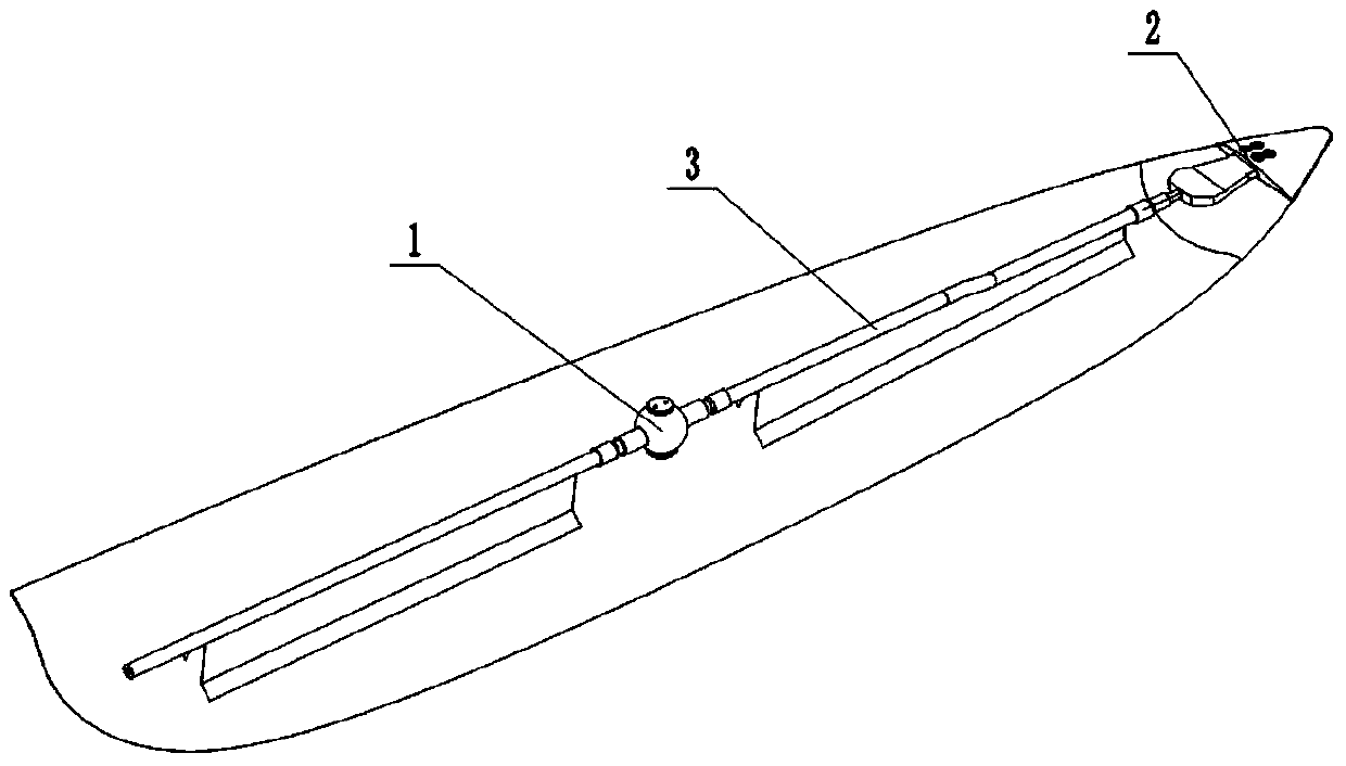
[0025] Basic as attached figure 1 Shown: a lightning protection system for wind power blades, including a blade body lightning-termination unit 1 , a blade-tip lightning-termination unit 2 and wires 3 .

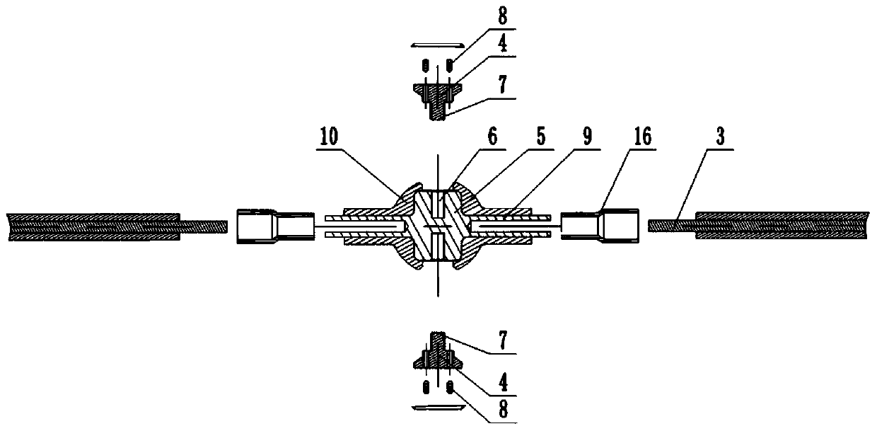
[0026] combine figure 2 As shown, the blade body air-termination unit 1 includes the blade body air-termination device 4 and the blade-body air-termination device base 5. Both the upper and lower end faces are provided with threaded holes 6 perpendicular to the end faces, and the lower end of the blade air-termination device 4 is provided with a threaded column 7 matching the threaded hole 6, and the threaded column 7 is threadedly connected with the threaded hole 6. Also be provided with aperture on 4, be provided with set screw 8 in the aperture. Metal tubes 9 are provided at both ends of the air-termination base 5 of the blade body, and an insulating sealing layer 10 is provided on the outer surface of the air-termination unit 1 of the blade body.

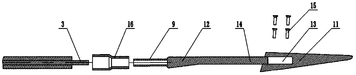
[0027] combine im...


PUM


Abstract

The invention relates to the technical field of lightning protection devices, and discloses a lightning protection system for a wind turbine blade. The lightning protection system comprises a blade body lightning arresting unit, a blade tip lightning arresting unit and a lead wire; the blade body lightning arresting unit comprises a blade body lightning arrester and a blade body lightning arresterbase; threaded holes perpendicular to the upper end surface and the lower end surface are correspondingly formed in the upper end surface and the lower end surface of the blade body lightning arrester base; threaded columns matched with the threaded holes are arranged at the lower end of the blade body lightning arrester; the blade tip lightning arresting unit comprises a blade tip lightning arrester and a blade tip lightning arrester base; a clamping groove is formed in the end part of the blade tip lightning arrester; a clamping block matched with the clamping groove is arranged at one endof the blade tip lightning arrester base; threaded holes are formed in the clamping block; and counterbores paired with the threaded holes in the clamping block are formed in the clamping groove. In the scheme, the blade body lightning arresting unit and the blade tip lightning arresting unit are separately connected in a matching manner, so that the surface-surface fit of the lightning arrestersand the lightning arrester bases is realized, the electrical contact area is sufficient, the lightning protection system is stable and reliable, and the phenomenon of sparking is prevented, so that abetter lightning protection effect is achieved.

Description

technical field [0001] The invention relates to the technical field of lightning protection equipment, in particular to a lightning protection system for wind power blades. Background technique [0002] Wind turbines are usually installed in open fields, and they are often struck by lightning during thunderstorms. Since the blades of wind turbines are at a higher position during rotation, it is necessary to install lightning protection systems on the blades of wind turbines. . [0003] At present, the lightning protection system of wind power blades is connected by a lightning protection wire to the lightning-terminating system at each position. Each blade has multiple sets of air-termination system on the blade body and one air-termination system on the tip of the blade. Each leaf-body air-termination system has two air-terminations, which are respectively distributed on the PS shell and the SS shell. Each leaf-body air-termination system is mainly composed of an air-termi...

Claims


Application Information

Patent Timeline
Patent Type & Authority Applications(China)
IPC IPC(8): F03D80/30F03D80/00F03D13/10
CPCF03D13/10F03D80/00F03D80/30Y02E10/72
Inventor 谢磊文蕾袁炜谷端冯钦陈千婷
Owner JILIN CHONGTONG CHENGFEI NEW MATERIAL
Why Eureka
Try Eureka