
Detection system capable of correcting light source, and light source correction method thereof

A technology for light source calibration and detection system, which is applied in the parts of TV systems, parts of color TVs, TVs, etc.

Inactive Publication Date: 2016-07-06
致茂电子(苏州)有限公司
View PDF5 Cites 3 Cited by
  • Summary
  • Abstract
  • Description
  • Claims
  • Application Information

AI Technical Summary

Problems solved by technology

The light source correction method includes adjusting the shooting field of view within the irradiation area

Method used

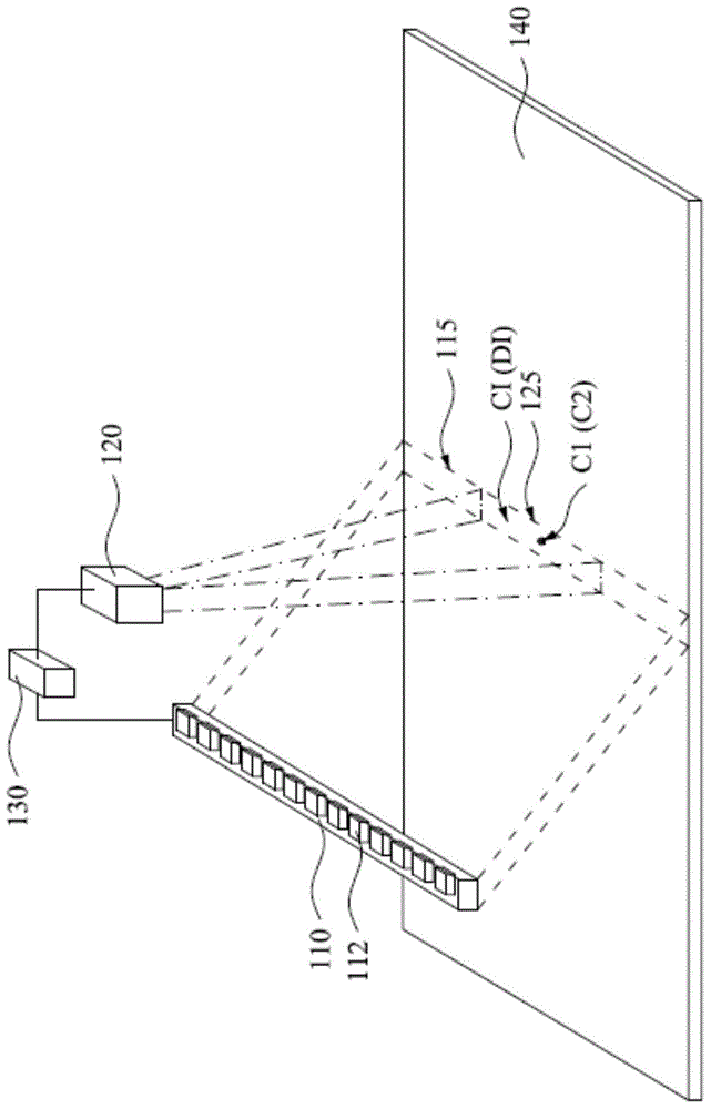
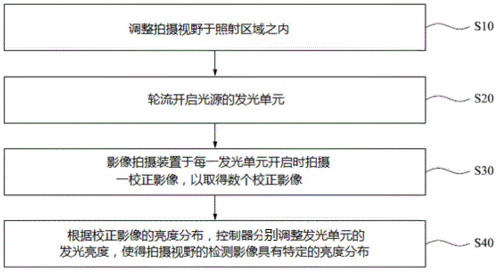
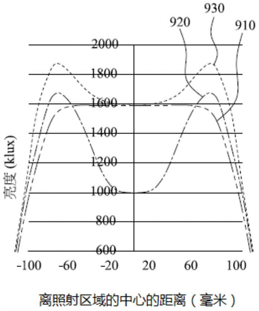

Image

  • Detection system capable of correcting light source, and light source correction method thereof
  • Detection system capable of correcting light source, and light source correction method thereof
  • Detection system capable of correcting light source, and light source correction method thereof

Examples


Embodiment Construction

[0025] A number of embodiments of the present invention will be disclosed in the following figures. For the sake of clarity, many practical details will be described together in the following description. It should be understood, however, that these practical details should not be used to limit the invention. That is, in some embodiments of the present invention, these practical details are unnecessary. In addition, for the sake of simplifying the drawings, some commonly used structures and components will be shown in a simple and schematic manner in the drawings.

[0026] figure 1 It is a three-dimensional schematic diagram of a detection system for a correctable light source according to an embodiment of the present invention. As shown in the figure, the detection system capable of correcting the light source includes a light source 110 , an image capturing device 120 and a controller 130 . The light source 110 includes a plurality of light emitting units 112 . The light...


PUM


Abstract

The invention discloses a light source correction method of a detection system. The detection system comprises a light source, an image shooting apparatus and a controller. The light source is provided with an irradiation area and the image shooting apparatus has a shooting visual field. The light source correction method comprises adjusting the shooting visual field to be in the irradiation area, unlatching multiple luminescence units of the light source by turns, the image shooting apparatus shooting a correction image when each luminescence unit is unlatched so as to obtain multiple correction images, according to brightness distribution of the correction images, the controller respectively adjusting brightness of the luminescence units so as to compensate the dark corner effect of the image shooting apparatus and enable detection images in the shooting visual field to have specific brightness distribution.

Description

technical field [0001] The invention relates to a method for correcting a light source of a detection system. Background technique [0002] The detection system is to irradiate the object under test with a light source, and take an image of the object under test to detect the quality of the object under test. At present, images of the object to be tested are mostly captured by a lens. However, since the brightness of the light after passing through the lens will decrease as it gets closer to the edge of the lens' field of view, it is difficult to analyze the details of the image formed at the edge of the field of view. Although the vignetting correction function of the software can be used to compensate the brightness of the edge of this image, but this also increases the noise of the edge image at the same time, and its signal-to-noise ratio (S / Nratio) cannot actually be improved. With the advancement of technology and the change of products, the requirements for the illu...

Claims


Application Information

Patent Timeline
Patent Type & Authority Applications(China)
IPC IPC(8): H04N17/00H04N5/235
Inventor 翁义龙朱建勋
Owner 致茂电子(苏州)有限公司
Learn More