
Intraocular lens assembly

A lens and component technology, applied in the field of intraocular lens components, can solve problems such as residual errors, inability to fully correct optical errors, and inability to achieve normal refraction

Active Publication Date: 2016-07-06
OCULENTIS HLDG
View PDF14 Cites 1 Cited by
  • Summary
  • Abstract
  • Description
  • Claims
  • Application Information

AI Technical Summary

Problems solved by technology

[0007] Known IOL systems and IOL systems often do not fully correct optical errors in the eye
Usually unable to achieve emmetropy (where light rays are focused precisely on the retina)
There is still residual error

Method used


Image

  • Intraocular lens assembly
  • Intraocular lens assembly
  • Intraocular lens assembly

Examples


Embodiment Construction

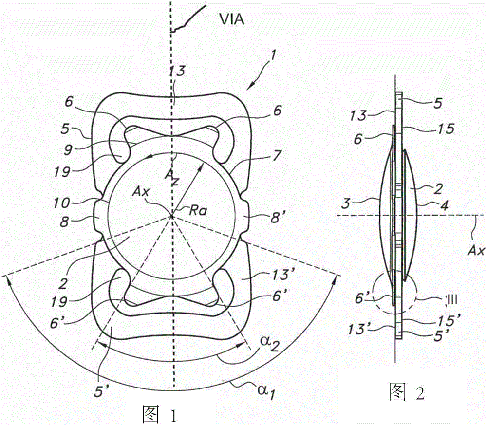
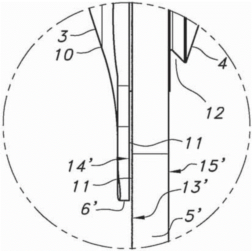
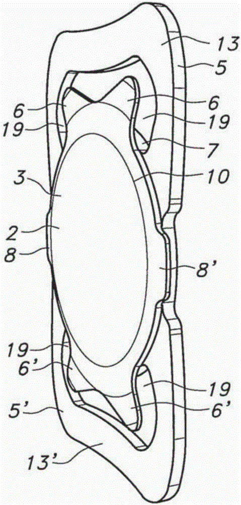
[0158] In this specification, the first relevant part of the eye will be in the Figure 39A , 39B and described in 39C. exist Figure 1-11 , the structure of the intraocular lens (IOL) and its location in the eye will be described ( Figure 9-11 ), and steps for placing such an IOL in the eye. exist Figure 12-35 In, some embodiments of intraocular lens assemblies will be described, which are based on Figure 1-11 The IOL.

[0159] Eye

[0160] exist Figure 39A with 39B In , a cross section through the eyeball 20 is schematically depicted. exist Figure 39A Here, eyeball 20 has cornea 21 , iris 25 , pupil 26 and capsular bag 22 with natural lens 31 . The pouch 22 has a front portion 23 and a rear portion 24 . exist Figure 39B , the eyeball 20 is shown after the natural lens 31 has been removed, leaving an empty capsular bag 22 with an opening 32, which is generally circular or oval. The opening 32 is in the front portion 23 of the pouch 22 . In many cases, the...


PUM


Abstract

The invention provides an intra ocular lens assembly comprising an intra ocular lens structure (IOL) for placement in the capsular bag and securing the IOL in an opening in an anterior part of a capsular bag, with an anterior capsular bag flap surrounding said opening, and a secondary intraocular lens (S-IOL) comprising fixing parts for attaching said S-IOL to said IOL.

Description

technical field [0001] The present invention relates to an intraocular lens assembly, including an intraocular lens structure (IOL) and a secondary intraocular lens, and methods for inserting such an intraocular lens assembly. Background technique [0002] During modern cataract surgery (which is also called extracapsular cataract extraction), a hole is cut in the anterior capsular bag. This can be done by using a laser device. Subsequently, the natural lens is removed. In many proposed procedures, an IOL is placed in the remainder of the capsular bag. The IOL is essentially located in the empty bag. [0003] Typically, an IOL is provided with haptics. These tentacles extend radially from the lens of the IOL. After implantation of the IOL, these tentacles typically engage at the inner periphery of the remaining capsular bag portion to substantially keep the optic of the IOL (eg, lens) centered and positioned within the capsular bag. [0004] To improve the fixation of ...

Claims


Application Information

Patent Timeline
Patent Type & Authority Applications(China)
IPC IPC(8): A61F2/16
CPCA61F2/1648A61F2002/1681A61F2220/0008A61F2/1601A61F2002/1689A61F2002/169A61F2002/16902
Inventor B·F·M·万德斯
Owner OCULENTIS HLDG
Learn More