A pipe multi-angle drilling equipment

A kind of drilling equipment, multi-angle technology, applied in the direction of drilling/drilling equipment, metal processing equipment, boring machine/drilling machine parts, etc., can solve the problems of low drilling accuracy, inconvenient processing, inconvenient distance control, etc. , to achieve the effect of improving drilling accuracy, improving drilling efficiency, and controlling drilling accuracy

Active Publication Date: 2019-01-11
江苏净傲机电科技有限公司
View PDF13 Cites 1 Cited by
  • Summary
  • Abstract
  • Description
  • Claims
  • Application Information

AI Technical Summary

Problems solved by technology

[0002] When drilling the surface of the pipe, if it is necessary to drill multiple holes on the surface of the pipe, the existing equipment usually needs to manually move the pipe, so that the drilling accuracy is not high. Some equipment adopts the method of manually rotating the pipe, which makes it inconvenient to control the distance between the holes, resulting in low product precision and inconvenient processing

Method used


Image

  • A pipe multi-angle drilling equipment

Examples


Embodiment 1

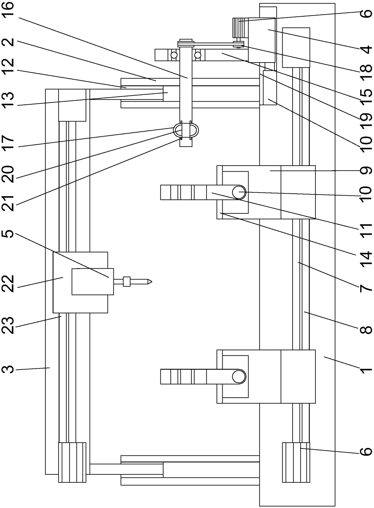
[0023] Such as figure 1 As shown, a pipe multi-angle drilling equipment includes a base 1 and a beam 3 arranged on the base, the beam is provided with a drilling device 5, and a pipe rotation device is provided on the base , a motor 6 is arranged on the base, a lead screw 7 is arranged on the rotating shaft of the motor, a fixed shaft 8 matched with the lead screw is arranged below the lead screw, and a A support platform 9 is provided on the bar, and the support platform is sleeved on the lead screw and the fixed shaft, and two hydraulic cylinders 10 arranged opposite to each other are arranged on the support platform. The expansion rods of the hydraulic cylinders are respectively provided with positioning buckles 11, the lower ends of the positioning buckles are fixedly connected to the hydraulic cylinders, the upper ends of the positioning buckles are semicircular, and the upper ends of the two hydraulic cylinders A circular structure is formed between the positioning buck...

Embodiment 2

[0031] In this embodiment, on the basis of Embodiment 1, in order to realize the rotation of the crossbar conveniently, preferably, a motor 6 and a reduction box matched with the motor are arranged on the upper end surface of the slider. The output shaft of the reduction box is provided with a pulley 18, and one end of the said cross bar protruding from the support is provided with a pulley, and the said reduction case drives the said cross bar to rotate by a belt. The belt pulley is driven to rotate by the motor, and the power transmission is realized by the belt, which drives the cross bar to rotate relative to the bracket. When the pipe needs to be rotated, slide the slider along the base, so that the slider drives the bracket to move towards the pipe. When the buckle on the cross bar is engaged with the inner side of the pipe, the starting motor drives the cross bar to rotate, so that the pipe rotates accordingly.

[0032]In this embodiment, in order to facilitate the move...


PUM


Abstract

The invention discloses a multi-angle drilling device for a pipe.The multi-angle drilling device comprises a base and a transverse beam arranged on the base.A drilling device body is arranged on the transverse beam, a pipe rotating device is arranged on the base, a motor is arranged on the base, a lead screw is arranged on a rotating shaft of the motor, a fixing shaft matched with the lead screw is arranged below the lead screw, a supporting platform is arranged on the lead screw and arranged on the lead screw and the fixing shaft in a sleeving mode, two opposite hydraulic cylinders are arranged on the supporting platform, positioning buckles are arranged on stretchable rods of the two hydraulic cylinders, and the lower ends of the positioning buckles are fixedly connected to the hydraulic cylinders.According to the multi-angle drilling device, a transverse rod is driven by the motor to rotate, the pipe is rotated, and multi-angle and multidirectional drilling operation can be conveniently carried out on the pipe in the radial direction; as the pipe is moved through the lead screw, the drilling accuracy can be improved in the axial direction of the pipe.

Description

technical field [0001] The invention relates to a pipe material multi-angle drilling equipment. Background technique [0002] When drilling the surface of the pipe, if it is necessary to drill multiple holes on the surface of the pipe, the existing equipment usually needs to manually move the pipe, so that the drilling accuracy is not high. Some equipment adopts the method of manually rotating the pipe, which makes it inconvenient to control the distance between the holes, resulting in low product precision and inconvenient processing. Contents of the invention [0003] The purpose of the present invention is to provide a multi-angle drilling equipment for pipes, which can improve the problems existing in the prior art. By using a motor to drive the cross bar to rotate, the rotation of the pipe is realized, which is convenient for multi-angle and multi-directional drilling in the radial direction of the pipe. Drilling operation, at the same time, due to the use of screw t...

Claims


Application Information

Patent Timeline
Patent Type & Authority Patents(China)
IPC IPC(8): B23Q1/30B23B47/20
CPCB23Q1/30B23Q5/28B23Q5/38
Inventor 任新庄
Owner 江苏净傲机电科技有限公司
Why Eureka
Try Eureka