Air purifying equipment joint control atomization system

A technology of air purification equipment and atomization system, which is applied in the direction of air humidification system, air conditioning system, heating and ventilation control system, etc. It can solve the problems of high cost, cumbersome control, and difficult adjustment of air humidity, and achieve simple installation and construction. Stable operation, intelligent and convenient operation

Inactive Publication Date: 2016-07-13
HEBEI AIJIE ENVIRONMENTAL PROTECTION TECH
View PDF10 Cites 5 Cited by
  • Summary
  • Abstract
  • Description
  • Claims
  • Application Information

AI Technical Summary

Problems solved by technology

[0002] For densely populated public places such as hospitals, hotels, commercial supermarkets, centralized office buildings of governments, enterprises and institutions, commercial office buildings, railway stations, trains, etc., the traditional fresh air system cannot achieve unified control, especially for the poor adjustment of air humidity. Another air humidity control system is used for control, and for the equipment that has already installed the fresh air system, if the addition of humidification equipment can only be done by installing an air humidifier indoors, the overall circulation function of the existing fresh air system cannot be fully utilized. It is unrealistic and costly to establish a humidification system. In addition, the two sets of control of the traditional humidifier and fresh air system are very cumbersome, which brings a huge workload to the temperature and humidity control of large public places.

Method used


Image

  • Air purifying equipment joint control atomization system
  • Air purifying equipment joint control atomization system
  • Air purifying equipment joint control atomization system

Examples


Embodiment Construction

[0035] In order to make the purpose of the present invention, technical solutions and advantages clearer, the following combination Figure 1~Figure 3 and specific examples to clearly and completely describe the invention.

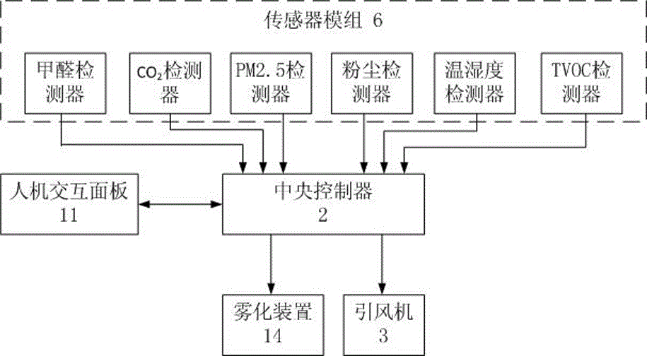
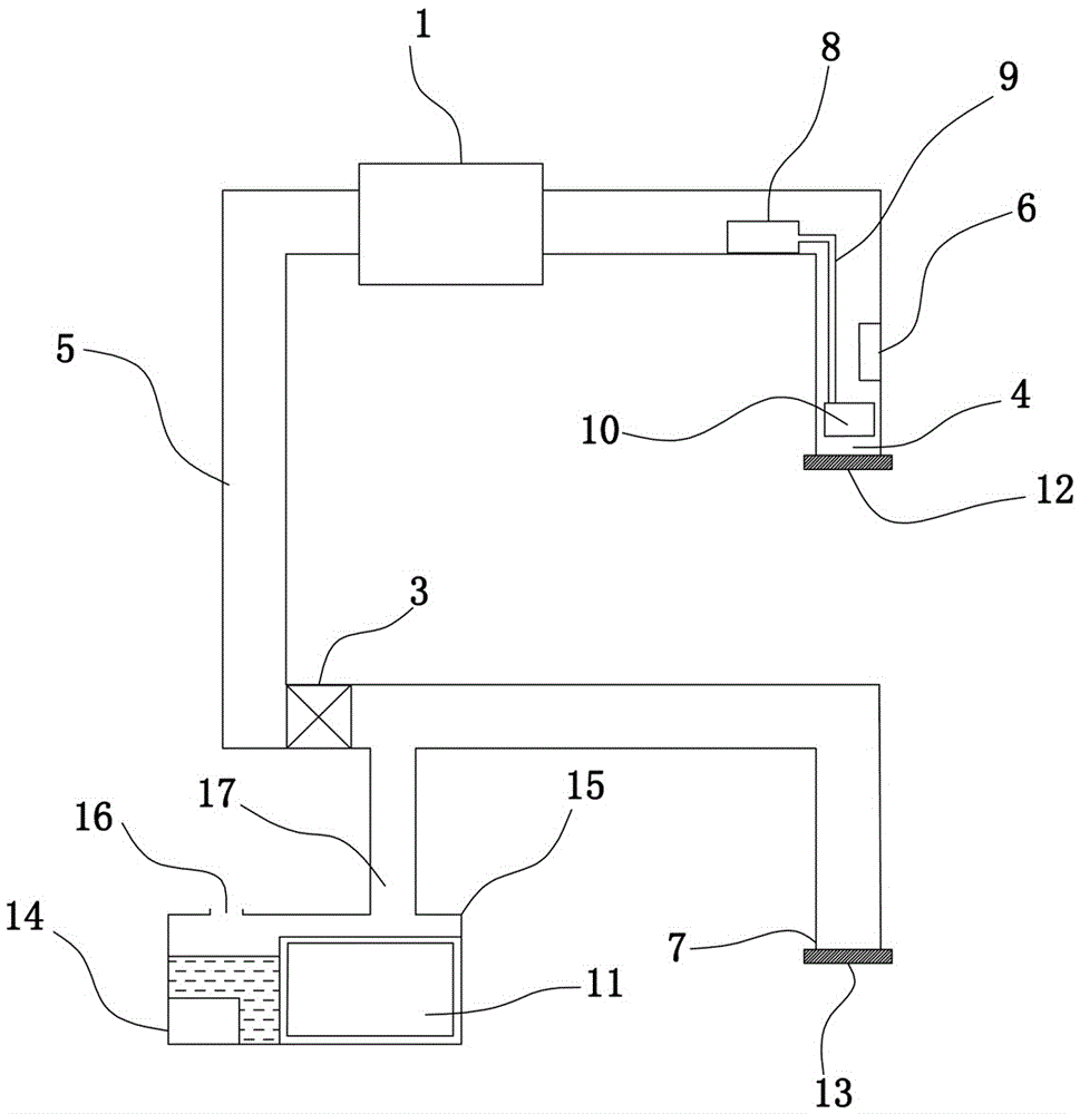
[0036] Such as Figure 1~Figure 3 As shown, the present embodiment includes a purification device 1 arranged in the air duct 5 of the central air conditioner, one end of the air duct 5 is an air inlet 7, and the other end is an air outlet 4, and it also includes a central controller 2, a human The machine interaction panel 11, the sensor module 6, the induced draft fan 3 arranged in the air duct 5, the water tank 15 communicated with the air duct 5 through the mist outlet pipe 17, and the atomization device 14 arranged in the water tank 15;

[0037] Each output end of the sensor module 6 is respectively connected to the corresponding input end of the central controller 14, and the man-machine interaction panel 11 and the central controller 14 are bidirect...


PUM


Abstract

The invention discloses an air purifying equipment joint control atomization system. The system comprises purifying equipment arranged in an air duct of a central air conditioner. One end of the air duct is provided with an air inlet, and the other end of the air duct is provided with an air outlet. The system further comprises a central controller, a human-computer interaction panel, a sensor module, an induced draft fan arranged in the air duct, a water tank communicated with the air duct through a mist discharging pipe and an atomization device arranged in the water tank. All output ends of the sensor module are connected with corresponding input ends of the central controller respectively. The human-computer interaction panel and the central controller are in bidirectional connection. The output end of the central controller is connected with the controlled end of the induced draft fan and the controlled end of the atomization device. The sensor module is introduced to timely monitor and record field data in real time, the central controller jointly controls the atomization device and the induced draft fan according to the actual environment in a room, the water tank provided with the atomization device is arranged, and by adding a disinfectant or refreshing agent into the water tank, bacteria, odor and peculiar smells are eliminated while humidification is achieved.

Description

technical field [0001] The invention relates to an air purification equipment joint control atomization system, which belongs to the field of atomization equipment. Background technique [0002] For densely populated public places such as hospitals, hotels, commercial supermarkets, centralized office buildings of governments, enterprises and institutions, commercial office buildings, railway stations, trains, etc., the traditional fresh air system cannot achieve unified control, especially for the poor adjustment of air humidity. Another air humidity control system is used for control, and for the equipment that has already installed the fresh air system, if the addition of humidification equipment can only be done by installing an air humidifier indoors, the overall circulation function of the existing fresh air system cannot be fully utilized. It is unrealistic and costly to establish a humidification system. In addition, the two sets of control of the traditional humidifi...

Claims


Application Information

Patent Timeline
Patent Type & Authority Applications(China)
IPC IPC(8): F24F11/00F24F3/16F24F6/12F24F13/28
CPCF24F3/16F24F6/12F24F13/28F24F11/30F24F11/54F24F11/62F24F2110/10F24F2110/20F24F2110/50F24F2110/64F24F2110/66F24F2110/70F24F8/10F24F8/117F24F8/24
Inventor 马辉李书学杨云栓姚亮闯
Owner HEBEI AIJIE ENVIRONMENTAL PROTECTION TECH
Why Eureka
Try Eureka