Contact lens restoring instrument

A technology for contact lenses and glasses room, applied in the directions of glasses/protective glasses, glasses/goggles, instruments, etc., which can solve the problems of not fundamentally solving the problem of waterproofing, liquid spillage, and difficulty in storing contact lenses.

Active Publication Date: 2016-07-13
SUZHOU SANGECHOUPIJIANG BIOLOGICAL TECH
View PDF6 Cites 11 Cited by
  • Summary
  • Abstract
  • Description
  • Claims
  • Application Information

AI Technical Summary

Problems solved by technology

However, there are many problems in the use of this cleaning device: 1) Since the power supply, circuit board and other electronic components are arranged in the housing, although it can prevent the cleaning agent (or contact lens care solution) from entering the housing, this top-heavy The structure makes it easy to rollover during the process of opening the shell and when the cleaning device is placed, causing the liquid to splash out; 2) The conductive part penetrates the shell from top to bottom and penetrates into the cleaning agent. The structure determines that the amount of cleaning agent must be at least in contact with the conductive parts. On the one hand, it is difficult for users to measure the amount of cleaning agent added, and on the other hand, it will inevitably cause waste of cleaning agent; Fundamentally solve the problem of waterproofing, it is difficult to store contact lenses and carry them with you, so users must purchase additional contact lens cases in actual use; 4) The cleaning device does not solve the airtight problem between the conductive parts and the housing , even if the electronic components are placed above the cleaning unit, it will inevitably cause liquid to enter the housing and damage the electronic components

Method used


Image

  • Contact lens restoring instrument
  • Contact lens restoring instrument
  • Contact lens restoring instrument

Examples


Embodiment 1

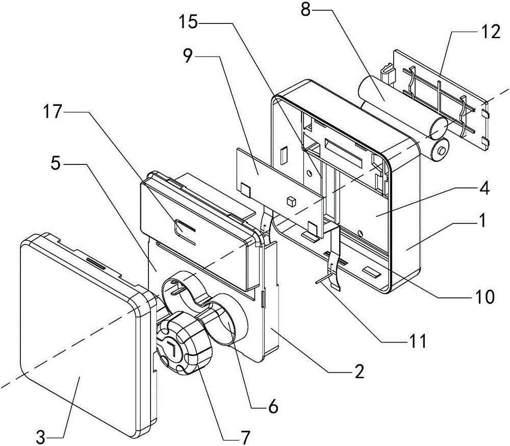
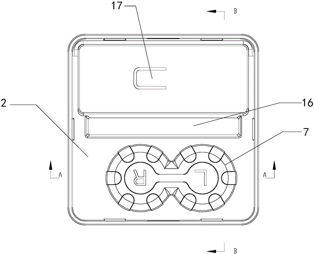
[0032] Such as Figure 1 to Figure 4 As shown, a contact lens reduction instrument according to a preferred embodiment of the present invention includes a base 1, a middle base 2, a cover 3 and a cleaning mechanism. The middle base 2 is closed above the base 1 and forms an electronic component with the base 1. Room 4, the cover body 3 is closed above the middle seat 2 and forms a glasses room 5 with the middle seat 2; the top surface of the middle seat 2 is provided with two accommodating grooves 6 for placing contact lenses and communicating with each other, accommodating A sealing cover 7 is fastened on the groove 6; the cleaning mechanism includes a power supply 8, a circuit board 9, a conductive sheet 10 and an electrode 11; the circuit board 9 is arranged in the electronic component room 4 and is electrically connected to the power supply 8; two, all arranged in the electronic component chamber 4, and one end thereof is electrically connected with the circuit board 9; the...

Embodiment 2

[0039] Such as Figure 1 to Figure 4 As shown, in a contact lens reduction instrument according to a preferred embodiment of the present invention, the electrodes 11 are usually arranged symmetrically at opposite ends of the two accommodating grooves 6, and stoppers are arranged on both sides of the electrodes on the accommodating grooves 6. Flow ridges to avoid impact on the electrode surface when the cleaning agent flows. The shape of the electrodes 11 can be columnar or sheet. Compared with the columnar electrodes, the production cost of the sheet-shaped electrodes is higher, and the contact area with the accommodating tank is larger. Therefore, in the present invention, the columnar electrodes are taken as an example for further description.

[0040] In order to prevent the cleaning agent from leaking due to poor sealing between the electrode and the holding tank, the outer surface of the electrode 11 is provided with a rough surface, which can be achieved in a variety of ...

Embodiment 3

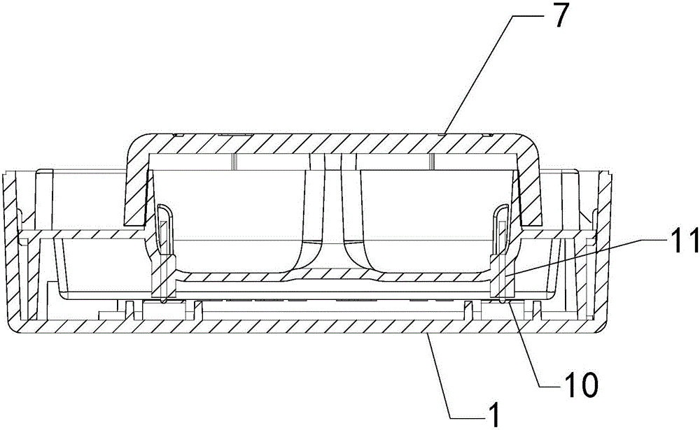
[0043] Such as Figure 1 to Figure 4 As shown, in a contact lens reducing instrument according to a preferred embodiment of the present invention, the position on the conductive sheet 10 that is in contact with the bottom of the electrode 11 is set as an elastic conductive part 14, and the implementation of the elastic conductive part can be various, for example , one end is bent upwards to contact the bottom of the electrode, and the elastic force of the bending position is used to realize the mutual pressure contact connection between the electrode and the conductive sheet (not shown in the figure); one end can also be tilted upward to contact the bottom of the electrode Contact, using the elastic recovery force of the deformation of the conductive sheet to realize the mutual pressing contact connection between the electrode and the conductive sheet (not shown in the drawings); Figure 4 As shown, the middle part can also be arched into an arc-shaped sheet, and the elastic f...


PUM


Abstract

The invention relates to a contact lens cleaning device, in particular to a contact lens restoring instrument.The contact lens restoring instrument comprises a base, a middle seat, a cover body and a cleaning mechanism, wherein two accommodating grooves are formed in the top surface of the middle seat; a sealing cover is fastened to each accommodating groove; the cleaning mechanism comprises a power supply, a circuit board, two conducting plates and two electrodes; the circuit board is arranged in an electronic element chamber and is electrically connected with the power supply; the two conducting plates are arranged in the electronic element chamber and one ends of the two conducting plates are electrically connected with the circuit board; the two electrodes are respectively arranged at the bottoms of the two accommodating grooves in a penetrating manner and are connected with the bottoms of the accommodating grooves in a sealed manner; the top ends of the electrodes are exposed out of the accommodating grooves while the bottom ends of the electrodes are exposed out of the electronic element chamber; and the bottom ends of the electrodes are electrically connected with the other ends of the conducting plates.The contact lens restoring instrument is reasonable in design, good in waterproofness and convenient to take along; a cleaning function and a storing function are combined; and meanwhile, contact lenses are cleaned effectively.

Description

technical field [0001] The invention relates to a contact lens cleaning device, in particular to a contact lens reduction instrument. Background technique [0002] There are quite a few myopic people who choose to use contact lenses for the sake of beauty or convenience. However, long-term use of contact lenses will cause protein deposition, which will cause the lenses to lose their oxygen permeability, and will cause damage to the cornea after wearing them. Therefore, after wearing contact lenses for a certain period of time, they must be cleaned for reuse. [0003] At present, the most commonly used cleaning method for contact lenses is to put the lenses of the contact lenses into the two containers of the contact lens cleaning box, respectively inject cleaning potions, and then rub them with your fingers to remove the dust and protein deposits on the lenses of the contact lenses. , mucus, oil and other dirt to maintain the oxygen permeability of the lens. However, the a...

Claims


Application Information

Patent Timeline
Patent Type & Authority Applications(China)
IPC IPC(8): G02C13/00
Inventor 孙碧霞
Owner SUZHOU SANGECHOUPIJIANG BIOLOGICAL TECH
Why Eureka
Try Eureka