Water dispenser liquid gravity energization control device

A control device and water dispenser technology, which is applied to beverage preparation devices, circuits, electric switches, etc., can solve the problems of high application cost, easy aging and failure of electronic components, etc., and achieve the effect of low application cost and stable and reliable control principle

Inactive Publication Date: 2016-07-13
边江
4 Cites 5 Cited by

AI-Extracted Technical Summary

Problems solved by technology

It solves the problem that the electronic components of the existing water shortage...

Abstract

Provided is a water dispenser liquid gravity energization control device. The water dispenser liquid gravity energization control device comprises a microswitch, a warp board, an external magnetic block, an internal magnetic block, an elastic component and a cylinder; one end of the warp board is movably installed on a microswitch body, the other end of the warp board is the free end, a touch point of the microswitch is located at the lower end of the warp board, and the warp board enables the touch point to switch between disconnection and connection through lifting or pressing; the external magnetic block is fixedly connected to the free end of the warp board; the internal magnetic block divides the inner cavity of the cylinder into a cavity A and a cavity B which are not communicated; a liquid inlet which is communicated with the cavity A is formed outside the cylinder; when the internal magnetic block moves along the inner wall of the cylinder in a one-way mode, magnetic force between the internal magnetic block and the external magnetic block is gradually increased; the elastic component is installed in the cavity B, and the elastic component is compressed or loosened along with movement of the internal magnetic block; the microswitch is located outside the cylinder and fixed relative to the cylinder. The water dispenser liquid gravity energization control device is used for controlling the energization state of an electric heater in a water dispenser, and the effects that when no water exists in a heating bin or the liquid level in the heating bin is lower than a certain height, the electric heater is deenergized, and when the liquid level in the heating bin reaches a certain height, the electric heater is energized are achieved.

Application Domain

Technology Topic

Image

  • Water dispenser liquid gravity energization control device
  • Water dispenser liquid gravity energization control device
  • Water dispenser liquid gravity energization control device

Examples

  • Experimental program(1)

Example Embodiment

[0021] Example 1:
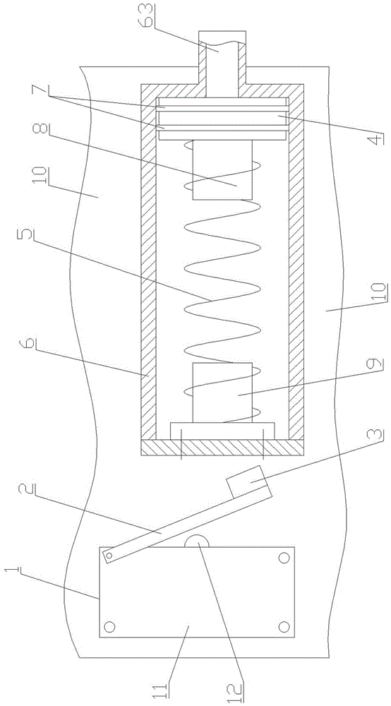
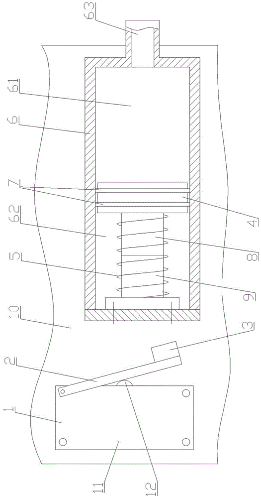
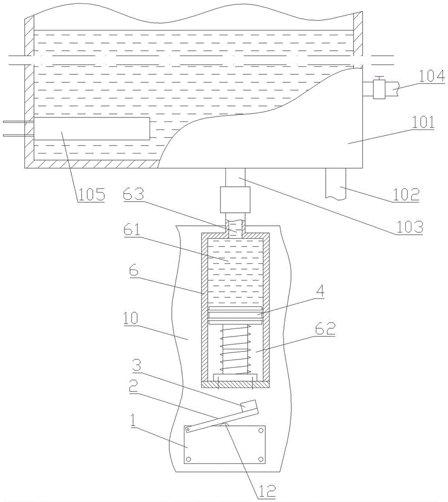
[0022] The water dispenser liquid gravity electrification control device includes a micro switch 1, a seesaw 2, an outer magnetic block 3, an inner magnetic block 4, an elastic element 5 and a cylinder body 6.
[0023] One end of the seesaw 2 is movably installed on the body 11 of the micro switch 1, and the other end is a free end. The contact 12 of the micro switch 1 is located at the lower end of the seesaw 2, and the seesaw 2 makes the contact 12 Toggles between open and closed. The outer magnetic block 3 is fixedly connected on the free end of the seesaw 2 and is opposite to the same magnetic pole of the inner magnetic block 4 . The inner magnetic block 4 is movably installed in the cylinder body 6, and it divides the inner chamber of the cylinder body 6 into chamber A61 and chamber B62 which are not connected to each other. The cylinder body 6 is provided with a liquid inlet 63 connected to the cavity A61. When the inner magnetic block 4 moves toward the outer magnetic block 3 along the inner wall of the cylinder body 6 , the magnetic force between it and the outer magnetic block 3 increases gradually. The elastic member 5 is installed in the cavity B62, which is compressed or relaxed as the inner magnetic block 4 moves. The micro switch 1 is located outside the cylinder body 6 and relatively fixed to the cylinder body 6 . Relatively fixed means that both the micro switch 1 and the cylinder body are fixed on the casing 10 .
[0024] The contact 12 of the micro switch 1 is the on/off key of the micro switch, which has two states of open and closed.
[0025] Preferably, a sealing ring 7 is provided between the inner magnetic block 4 and the inner wall of the barrel 6 .
[0026] Preferably, the elastic element 5 is a spring.
[0027] Preferably, the inner magnetic block 4 is connected with a boss C8 on the end surface on one side of the cavity B62, the cavity B62 is provided with a boss D9 corresponding to the position of the boss C8, one end of the spring is installed on the boss C8, and the other end is installed on the boss C8. On stage D9.
[0028] Briefly describe the installation and working principle of the present invention on the water dispenser: as image 3 As shown, the lower end of the heating chamber 101 of the water dispenser is provided with a water inlet 102 and a cylinder connecting port 103 , the side wall of the heating chamber 101 is provided with a water outlet 104 with a valve, and an electric heater 105 is arranged in the heating chamber 101 .
[0029] like image 3 As shown, the liquid inlet 63 of the cylinder 6 is connected to the cylinder connection port 103 of the heating chamber 101 through a joint, and the cylinder 6 is in a vertical state.
[0030] As the liquid level in the heating chamber 101 rises, the gravity of the water received by the inner magnetic block 4 gradually increases, and the gravity of the water eventually overcomes the elastic force of the elastic element 5, so that the inner magnetic block 4 moves downward in the cylinder body 6, and the inner and outer magnetic blocks 4 move downward. As the distance between the outer magnetic blocks gets closer, the repulsive force between the inner and outer magnetic blocks increases accordingly. Finally, the outer magnetic block 3 pushes down the seesaw 2 under the action of the repulsive force, and the contact 12 of the micro switch 1 is switched to the connected state. The electric heater 103 is energized.
[0031] When the liquid level in the heating chamber 101 is low, the gravity of the water that the inner magnetic block 4 is subjected to is less, and it does not move or moves a little, and the distance between the inner and outer magnetic blocks is so far that the repulsive force between the two is not enough When the seesaw 2 is pressed down, the contact 12 of the micro switch 1 remains open, and the electric heater 103 is in a power-off state.

PUM

no PUM

Description & Claims & Application Information

We can also present the details of the Description, Claims and Application information to help users get a comprehensive understanding of the technical details of the patent, such as background art, summary of invention, brief description of drawings, description of embodiments, and other original content. On the other hand, users can also determine the specific scope of protection of the technology through the list of claims; as well as understand the changes in the life cycle of the technology with the presentation of the patent timeline. Login to view more.

Similar technology patents

Classification and recommendation of technical efficacy words

Why Eureka
Try Eureka