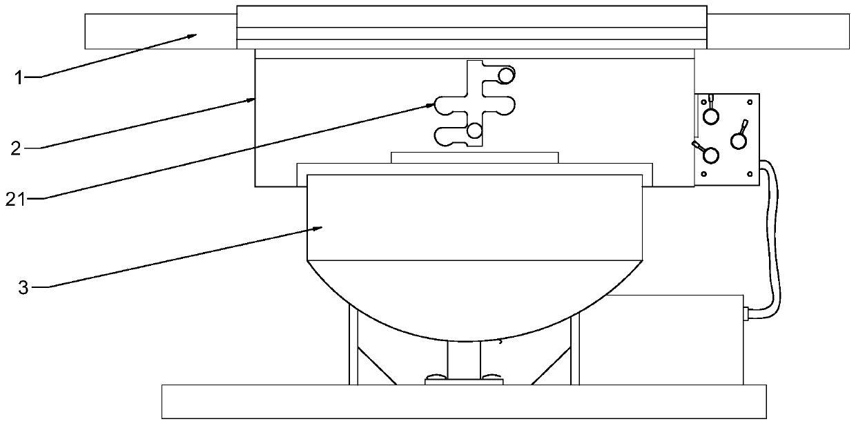
A single-motor-driven workbench for a machine tool
A single-motor-driven, workbench technology, applied in the direction of manufacturing tools, metal processing equipment, metal processing machinery parts, etc., can solve the problems of increasing the development and design cost of machine tool control systems and system failures, and achieve simple and reliable control principles and reduce design costs. cost effect
- Summary
- Abstract
- Description
- Claims
- Application Information
AI Technical Summary
Problems solved by technology
Method used
Image

Examples
Embodiment 1
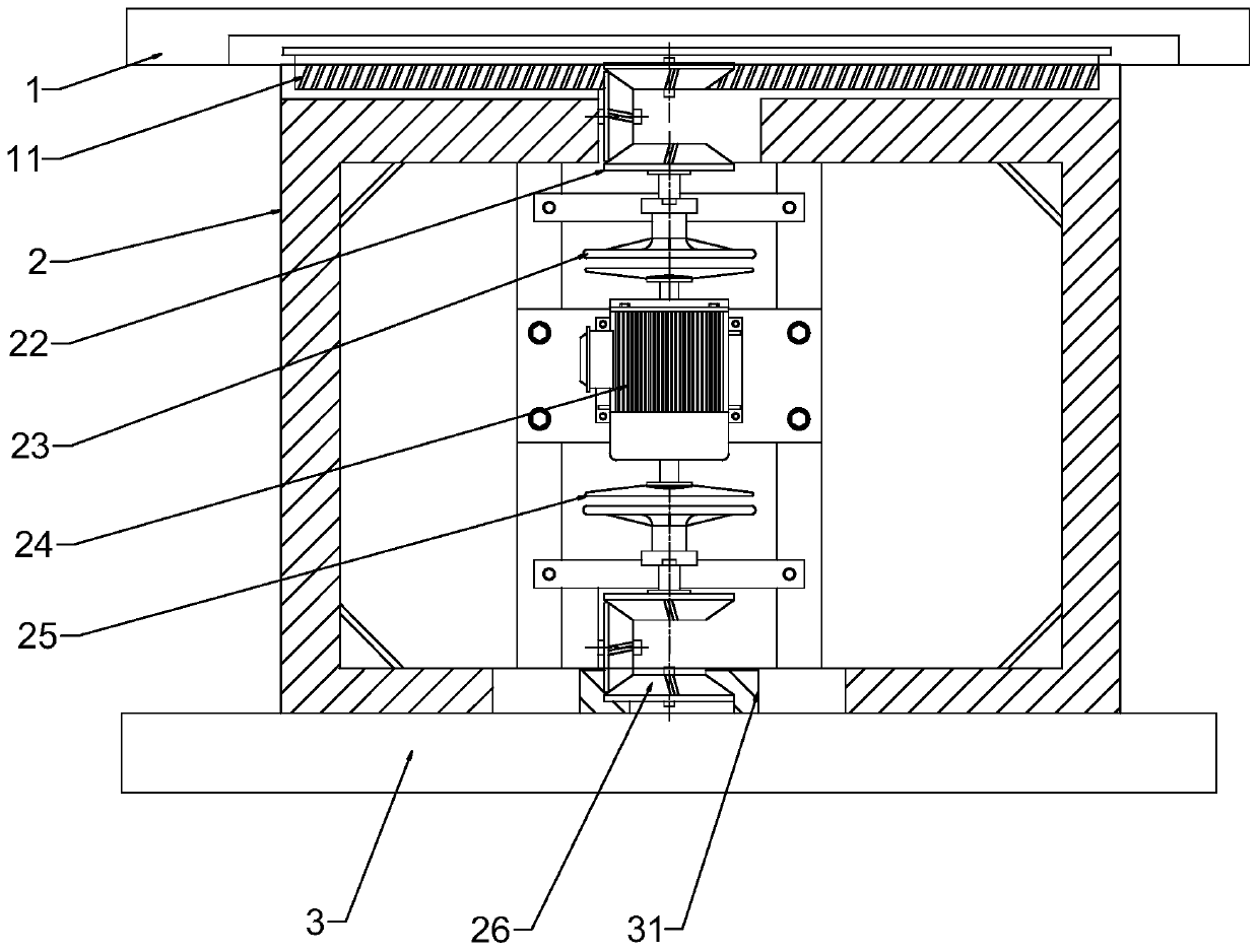
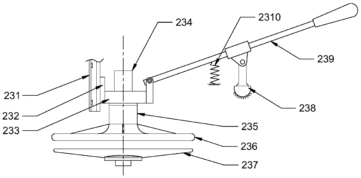
[0025] Embodiment 1, when it is necessary to separately drive the movement of the worktable body 1 (X axis), the upper and lower grinding discs in the upper action mechanism 23 will be in contact, and the upper and lower grinding discs in the lower action mechanism 25 will be separated. When the servo motor is running, only the upper action mechanism 23 and the uploading The actuating mechanism 22 acts to move the workbench body 1. When moving in the reverse direction, it is only necessary to control the reverse rotation of the biaxial servo motor 24.
Embodiment 2
[0026] Embodiment 2, when it is necessary to move the workbench body 1 in another direction (Y axis), the upper and lower grinding discs in the upper action mechanism 23 are separated, and the upper and lower grinding discs in the lower action mechanism 25 are in contact. When the servo motor is running, only the lower action mechanism is driven. 25 and the lower transmission mechanism 26 actions, so that the upper drive base 2 moves along the direction of the second rack 31. Similarly, when moving in the opposite direction, it is necessary to control the biaxial servo motor 24 to reverse.
Embodiment 3
[0027] Embodiment 3, when the workbench is far away from the machining spindle, the workbench body 1 and the upper driving seat 2 can be simultaneously driven to move the workpiece quickly to a position close to the spindle, and then adjusted, which can save time for workpiece positioning, To improve efficiency, the specific operation is to contact the grinding discs of the upper and lower action mechanisms.
PUM
 Abstract
Description
Claims
Application Information