A feeder tray grabbing mechanism for a multifunctional machine

A technology of grabbing mechanism and feeder, applied in the direction of electrical components, electrical components, etc., can solve the problems affecting the production efficiency of the feeder, and achieve the effect of simple structure, low cost and convenient operation

Active Publication Date: 2018-06-08
JIANGSU TORSUNG M&E
View PDF4 Cites 0 Cited by
  • Summary
  • Abstract
  • Description
  • Claims
  • Application Information

AI Technical Summary

Problems solved by technology

Among them, whether the grabbing structure can accurately and quickly grab and fix the tray will affect the production efficiency of the feeder

Method used


Image

  • A feeder tray grabbing mechanism for a multifunctional machine
  • A feeder tray grabbing mechanism for a multifunctional machine
  • A feeder tray grabbing mechanism for a multifunctional machine

Examples


Embodiment 1

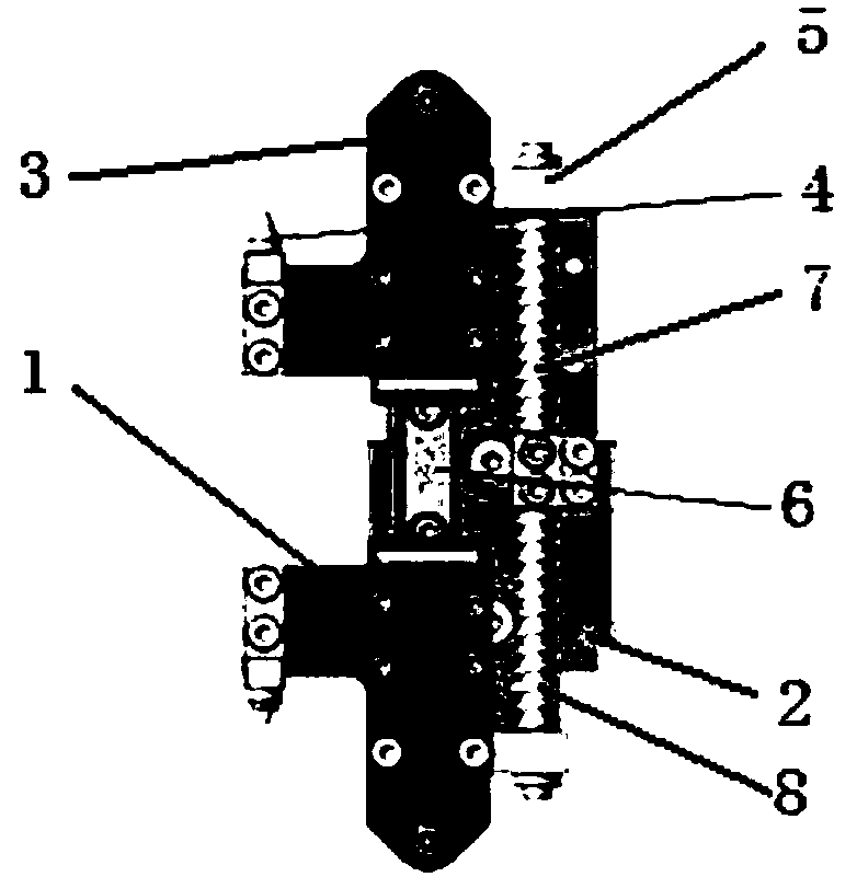
[0024] refer to figure 1 , a feeder tray grabbing mechanism for a chip mounter, the grabbing mechanism includes a pair of jaws 1 and a base 2 . The jaw 1 includes a slider 3, a positioning pin 4 and a sliding sleeve 5 fixed on the slider 3, and the base 2 is provided with two jaw guide rails 6, two guide posts 7 and two clamping jaws. The spring 8, the two jaw guide rails 6, the two guide posts 7 and the two clamping springs 8 are arranged end to end opposite to each other. When the base 2 is combined with a pair of jaws 1, the slider 3 is matched with the jaw guide rail 6, the sliding sleeve 5 is matched with the guide post 7, and the clamping spring 8 is set on the guide post 7 and press it tightly so that the pair of jaws 1 are separated from each other.

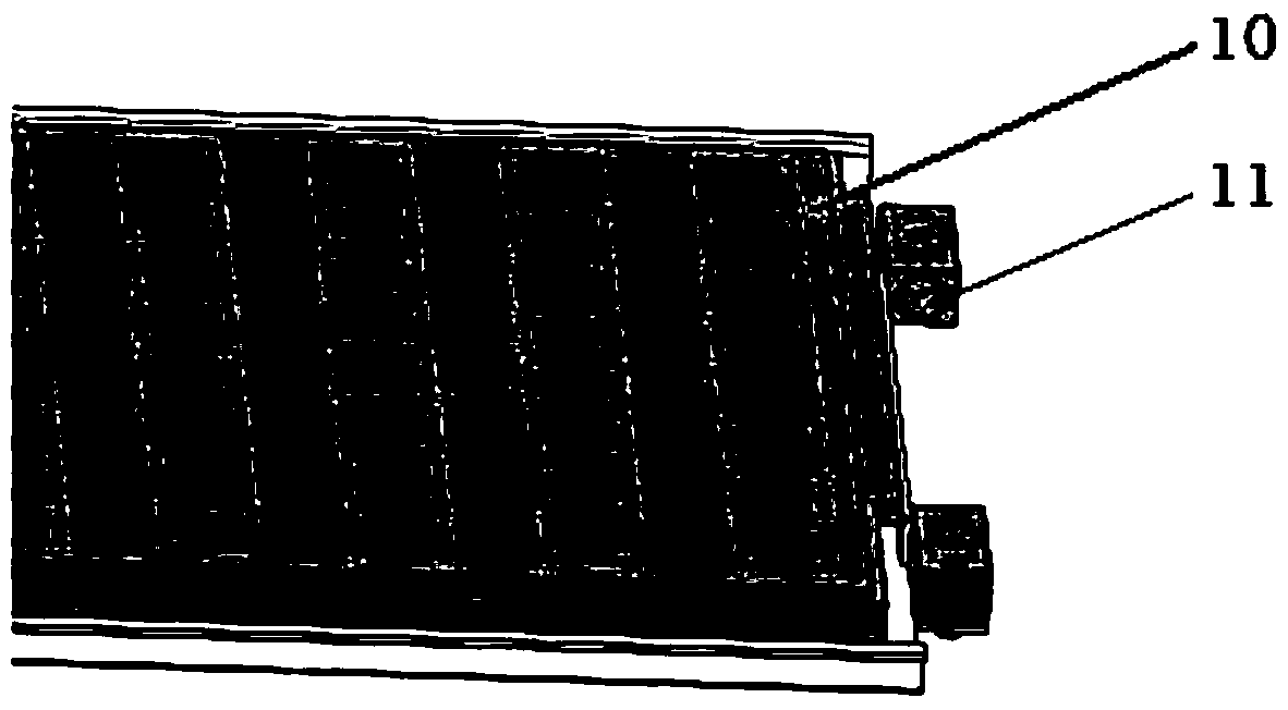
[0025] refer to figure 2 , the tray 10 matched with the tray grabbing mechanism is provided with a tray grabbing positioning hole 11 at a corresponding position.

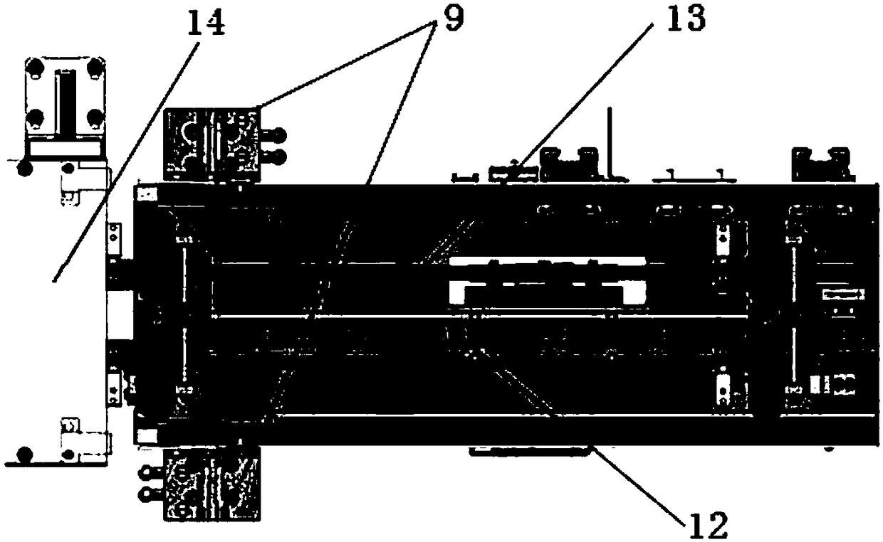
[0026] refer to image 3 , the relative movement of...


PUM


Abstract

The invention relates to the mechanical technical field of chip mounters and provides a chip mounter material feeder material disc catching mechanism comprising a pair of clamping jaws and a pedestal. Each clamping jaw comprises a slide block, a positioning pin, and a slide sleeve, wherein the positioning pin and the slide sleeve are fixed to the slide block. The pedestal is equipped with two clamping jaw guide rails, two guide pillars, and two clamping springs. The two clamping jaw guide rails are arranged end to end. The two guide pillars are arranged end to end. The two clamping springs are arranged end to end. When the pedestal and the pair of clamping jaws are combined, the slide blocks and the clamping jaw guide rails cooperate, the slide sleeves and the guide pillars cooperate, and the clamping springs sleeve the guide pillars and are compacted so that the pair of clamping jaws get close to each other or are separated. The chip mounter material feeder material disc catching mechanism is simple in structure, low in cost and convenient to operate, may achieve accurate positioning and automatic material disc catching, and uninterrupted material feeding.

Description

technical field [0001] The invention relates to the technical field of chip mounters, in particular to a feeder for a multifunctional chip mounter. Background technique [0002] The placement machine is a device that places the patch components on the corresponding position of the circuit board. There are many factors that affect the production efficiency of the multi-function placement machine, and the feeding mechanism of the multi-function placement machine is one of the important factors. At present, without considering the feeding problem, the placement head of the placement machine can quickly and accurately perform the placement operation in a short period of time, which requires the feeder of the placement machine to quickly and uninterruptedly supply Chip feeder. [0003] With the development of electronic technology, circuit boards are becoming more and more complex, and it is often necessary to paste or weld a variety of patch components of different sizes and t...

Claims


Application Information

Patent Timeline
Patent Type & Authority Patents(China)
IPC IPC(8): H05K13/04
CPCH05K13/0404
Inventor 孔金寿
Owner JIANGSU TORSUNG M&E
Why Eureka
Try Eureka