Thumb hole mold plate and method for applying same

A template and thumb technology, which is applied in the field of clothing equipment, can solve the problems of complexity, aggravating the work burden of operators, and low clothing production efficiency, and achieve the effect of simplifying the sewing process, facilitating the thumb hole sewing operation, and reducing the work burden

Active Publication Date: 2016-07-20
NINGBO SHENZHOU KNITTING
View PDF6 Cites 0 Cited by
  • Summary
  • Abstract
  • Description
  • Claims
  • Application Information

AI Technical Summary

Problems solved by technology

[0003] However, such a structure is more complicated in specific sewing. It takes multiple sewing steps to sew the front, rear, and bottom panels together to form a thumb hole structure. In mass production, Multiple sewing steps lead to low production efficiency of clothes and increase the workload of operators. Therefore, there is a need for a method that can easily and conveniently sew the front cloth, rear cloth and bottom cloth to each other to make thumb holes. Structural formwork to reduce the workload of operators

Method used


Image

  • Thumb hole mold plate and method for applying same
  • Thumb hole mold plate and method for applying same
  • Thumb hole mold plate and method for applying same

Examples


Embodiment Construction

[0040] In order to make it easy to understand the technical means, creative features, goals and effects achieved by the present invention, the following examples are combined with the appended Figures 1 to 12 The thumb hole template provided by the present invention is described in detail.

[0041] Hereinafter, embodiments of the present invention will be described with reference to the drawings. In the embodiments, parts of the same configuration are given the same reference numerals and descriptions are omitted.

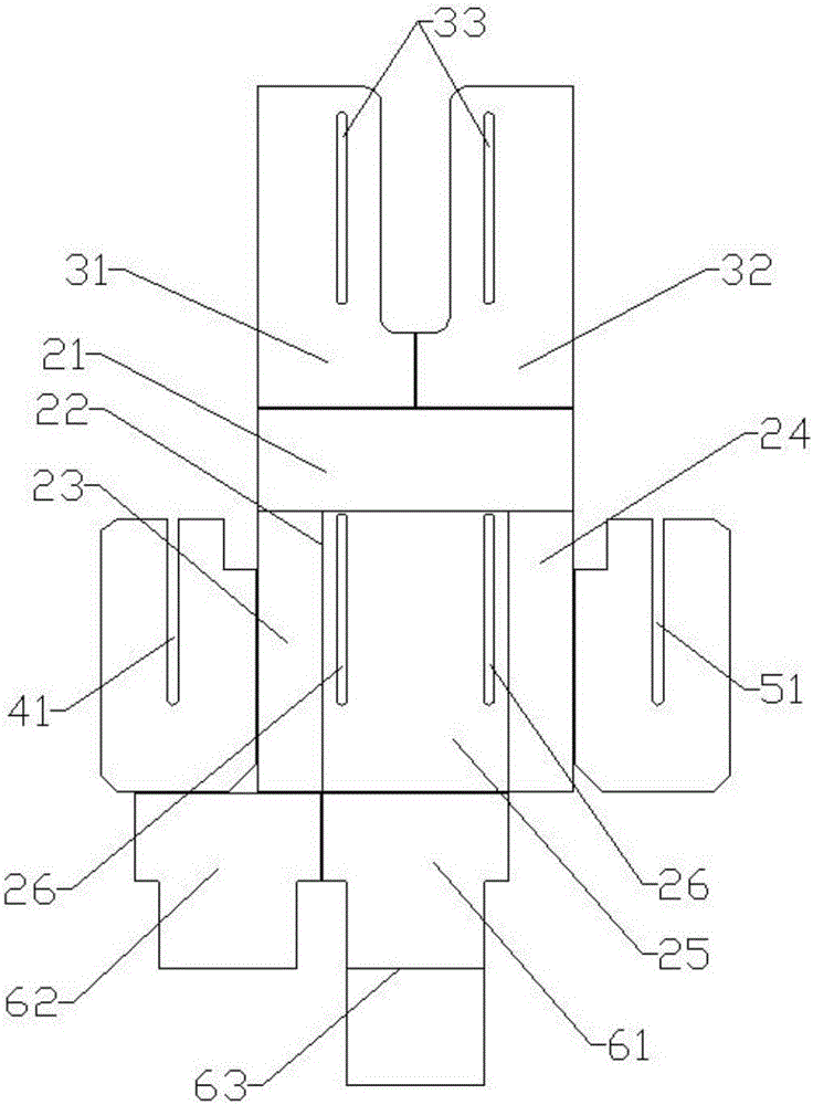
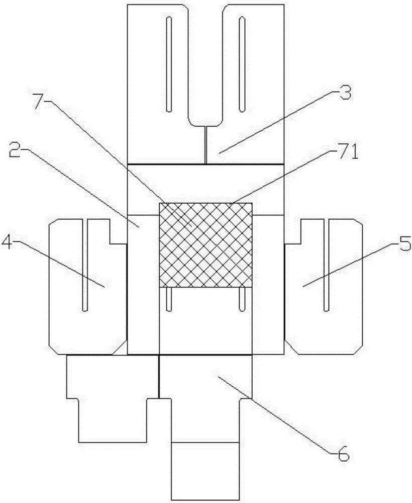
[0042] figure 2 It is a schematic diagram of the unfolded structure of an embodiment of a thumb hole template, Figure 3 to Figure 11 It is a specific application state diagram of an embodiment of a thumb hole template, such as Figure 2 to Figure 11 as shown in

[0043] The thumb hole template provided by the present invention includes a middle bottom plate 2 , an upper movable plate 3 , a lower movable plate 6 , a left movable plate 4 , and a right movable ...


PUM


Abstract

The invention discloses a thumb hole mold plate and a method for applying the same. The thumb hole mold plate comprises an intermediate bottom plate, an upper movable plate, a left movable plate, a right movable plate and a lower movable plate. The intermediate bottom plate is of a structure with three thicknesses and four plates including an upper plate, a left plate, a right plate and a grooved plate, and two parallel first needle channels are arranged on the grooved plate in a through manner along the depth direction of the grooved plate; the upper movable plate comprises a left upper plate and a right upper plate, second needle channels are respectively arranged on the left upper plate and the right upper plate in a through manner, and the left upper plate and the right upper plate can be turned over to cover the intermediate bottom plate; the left movable plate and the right movable plate can be turned over to cover the intermediate bottom plate, and a third needle channel and a fourth needle channel are respectively arranged on the left movable plate and the right movable plate in a through manner; the lower movable plate comprises a first lower side plate and a second lower side plate which are of 'convex' structures, and the second lower side plate can be turned over to be arranged on the grooved plate after being turned over to cover the first lower side plate. According to the technical scheme, the thumb hole mold plate and the method have the advantages that sewing procedures can be simplified to a great extent by the aid of the thumb hole mold plate, thumb hole sewing operation can be easily, conveniently and quickly completed, and workload on operators can be relieved.

Description

technical field [0001] The invention relates to the technical field of garment-making equipment, in particular to a thumb hole template and a method for using the same. Background technique [0002] With the gradual popularization of health and sports concepts, people pay more and more attention to sports and leisure in clothing. At present, thumb holes are designed on many clothes, especially sports hoodies. figure 1 It is a structural schematic diagram of a sleeve with a thumb hole in the prior art, such as figure 1 As shown in , the sleeve part with the thumb hole is mainly made by sewing the front panel 11, the rear panel 12, and the bottom panel 10, and the front panel 1 and the rear panel 12 are all sewn on the bottom panel 10, at the same time, an unsewn thumb hole 13 is formed between the front cloth piece 11 and the back cloth piece 12, and the front cloth piece 11 is used as a part of the cuff, so that the thumb can be passed through the thumb hole 13 alone during...

Claims


Application Information

Patent Timeline
IPC IPC(8): A41H3/01A41H43/02A41D27/10
CPCA41D27/10A41H3/01A41H43/02
Inventor 史尚雷陈勇张世堂王仕义陈芝芬
Owner NINGBO SHENZHOU KNITTING
Why Eureka
Try Eureka