Optical fiber induction layer and monitoring system thereof

A technology of optical fiber sensing and optical fiber, which is applied in the direction of transmitting sensing components, application, and measuring force by using optical devices, and can solve the problems of optical fiber sensing layer to distinguish sensing blind areas, small application range, and uneven sensing sensitivity

Active Publication Date: 2016-07-20
HUIJIA HEALTH LIFE TECH
View PDF8 Cites 11 Cited by
  • Summary
  • Abstract
  • Description
  • Claims
  • Application Information

AI Technical Summary

Problems solved by technology

[0005] The purpose of the present invention is to provide an optical fiber sensing layer, aiming to solve the problems of the prior art that the optical fiber sensing layer distinguishes the sensing blind area, the sensing resolution of the sensing layer is inconsistent, the sensing sensitivity is uneven, and the application range is small.

Method used


Image

  • Optical fiber induction layer and monitoring system thereof
  • Optical fiber induction layer and monitoring system thereof
  • Optical fiber induction layer and monitoring system thereof

Examples


no. 1 approach

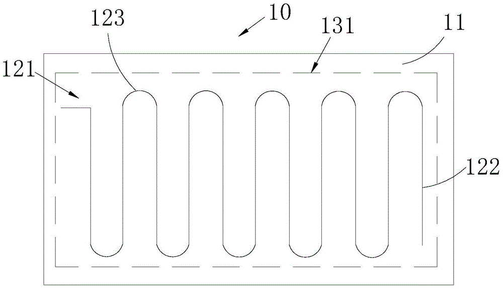
[0047] Such as image 3 with Figure 4 As shown, the diameters of the bends 121 and 123 of the same optical fiber row section 122 on the same interlayer 13 are equal, so that the diameters of the bends 123 are equal and change regularly, which is beneficial to the arrangement of the wiring 121 on the same optical fiber row section 122; the same interlayer The diameters of the bends 123 of the routing 121 of different fiber segments 122 on 13 gradually increase or decrease along the second direction, because the fiber segment 122 with the smaller diameter of the bend 123 gradually fills up and fits into the diameter of the larger bend 123 In the optical fiber line section 122, therefore, the routing 121 of the optical fiber line section 122 on the pressure sensitive component film 11 in this embodiment will show a transition trend in which the diameter of the bend 123 gradually increases or decreases, so that the pressure sensitive component film 11 The routing 121 of the opti...

no. 2 approach

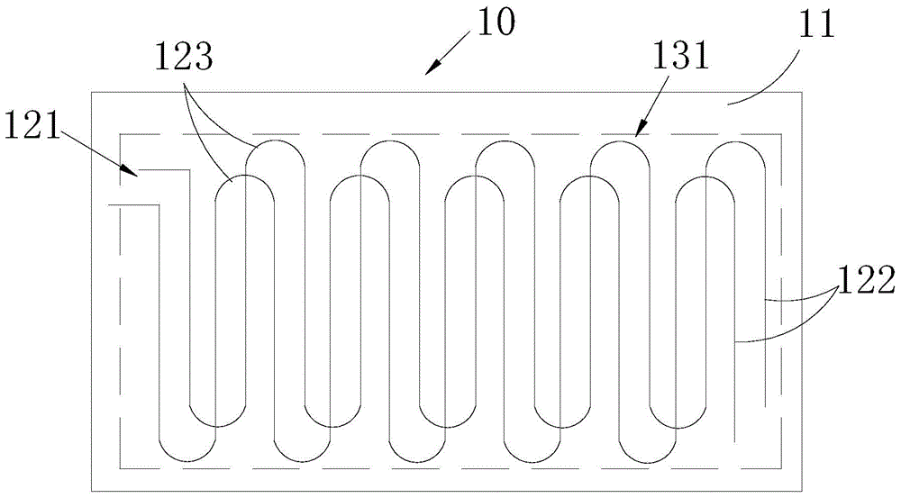
[0049] Such as image 3 with Figure 5 As shown, the diameters of the bends 123 of the wires 121 on all fiber segments 122 in the same interlayer 13 are equal. In this way, the diameters of the bends 123 of all the optical fiber segments 122 are equal and change regularly, which is conducive to the regular, uniform and relatively dense distribution of the lines of the optical fiber segments 122 on the pressure sensitive component film 11. Similarly, the above-mentioned optical fiber sensing layer 10 The sensitivity is uniform, the light attenuation value is relatively consistent, the sensitivity is high and adjustable, and the resolution is high.

no. 3 approach

[0051] Such as image 3 with Image 6 As shown, the diameters of the bends 123 of the wires 121 on the same optical fiber row section 122 in the same interlayer 13 are different, and two adjacent optical fiber row sections 122 are symmetrical about the center. In this way, every two optical fiber row segments 122 form a group of segments, and multiple groups of segments are distributed in parallel on the pressure sensitive component film 11. Similarly, the regular changes of the optical fiber row segment 122 routing 121 are conducive to making the above-mentioned optical fiber sensing layer 10 sensitive. The brightness is uniform, the light attenuation value is relatively consistent, the sensitivity is high and adjustable, and the resolution is high.


PUM


Abstract

The invention relates to the technical field of an optical fiber induction layer. The optical fiber induction layer provided by the invention comprises an upper pressure-sensitive component thin film and a lower pressure-sensitive component thin film which are superposed, and at least one soft smooth thin film by which a space between the two layers of the pressure-sensitive component thin films is divided into at least two compartments; at least one optical fiber moving segment, which extends in a first direction and comprises a plurality of sections which are subjected to S-shaped serial wiring, is arranged in the same compartment, and wiring elbows of upper and lower adjacent optical fiber moving segments are superposed in a staggered mode. The optical fiber moving segments are uniformly distributed on the pressure-sensitive component thin films of the optical fiber induction layer, so that optical fiber induction regions are formed, and since the wiring elbows of the upper and lower optical fiber moving segments are superposed in a staggered mode, an induction blind area can be mutually filled up by the various optical fiber induction regions, so that the optical fiber induction layer, breaking through the characteristic that an optical fiber is easily broken, can be used for rapidly and accurately detecting breath, heartbeats, sleep, temperature and humidity; and the optical fiber induction layer has the characteristics of being high and adjustable in sensitivity, high in resolution, anti-electromagnetic-interference and uniform in sensitivity. The invention also provides a monitoring system, and the monitoring system comprises the optical fiber induction layer, a light source, a light detection component, an optical fiber transmission loop and a processing circuit.

Description

technical field [0001] The invention belongs to the technical field of optical fiber sensing layer, and in particular relates to an optical fiber sensing layer and a monitoring system. Background technique [0002] In recent years, with the development of optical fiber sensing layer monitoring technology, the optical fiber sensing layer can be used to detect human breathing, heartbeat, sleep, etc., and has been gradually applied to the field of household products, such as baby pads, seat cushions, etc. [0003] Take the human respiration monitoring mattress with optical fiber sensing layer as an example, its appearance is a kit, and the kit is equipped with an optical fiber sensing layer. The optical fiber sensing layer includes optical fiber and upper and lower layers of grids. , the optical fibers are arranged parallel to each other in the grid to form a sensing area. In this way, when the human body is pressed on the mattress, as the human body breathes, the upper and low...

Claims


Application Information

Patent Timeline
Patent Type & Authority Applications(China)
IPC IPC(8): A61B5/00A61B5/0205A61B5/01
CPCA61B5/0205A61B5/6891A61B5/6804A61B2562/0271A61B2562/029G01L1/242G01D5/35374A61B2562/0266A61B5/0059A61B5/02055A61B5/0873A61B5/6892A61B2562/0247A61B5/1102G01D5/353
Inventor 杨淑贞
Owner HUIJIA HEALTH LIFE TECH
Why Eureka
Try Eureka