Drilling vessel assembly for edge-thinned lens

A drilling dish and lens technology, which is applied in the field of thin-edge lens drilling dish components, can solve the problems of uneven thickness, unreliable positioning, and offset.

Active Publication Date: 2016-07-20
GUANGDONG KINGDING OPTICAL TECH CO LTD
View PDF7 Cites 1 Cited by
  • Summary
  • Abstract
  • Description
  • Claims
  • Application Information

AI Technical Summary

Problems solved by technology

[0002] With the development of science and technology today, in the processing of optical glass spherical lenses, the thickness of the lens is getting thinner and thinner. For a lens with an edge width of less than 0.4mm (hereinafter referred to as a thin edge lens), it is processed by a drilling dish. At the same time, due to the thinner edge of the lens and the shallower depth of the edge of the counterbore of the drilling dish, the lens is easily shifted when it is placed on the drilling dish, so that it cannot be positioned reliably. Uneven phenomenon

Method used


Image

  • Drilling vessel assembly for edge-thinned lens
  • Drilling vessel assembly for edge-thinned lens
  • Drilling vessel assembly for edge-thinned lens

Examples


Embodiment Construction

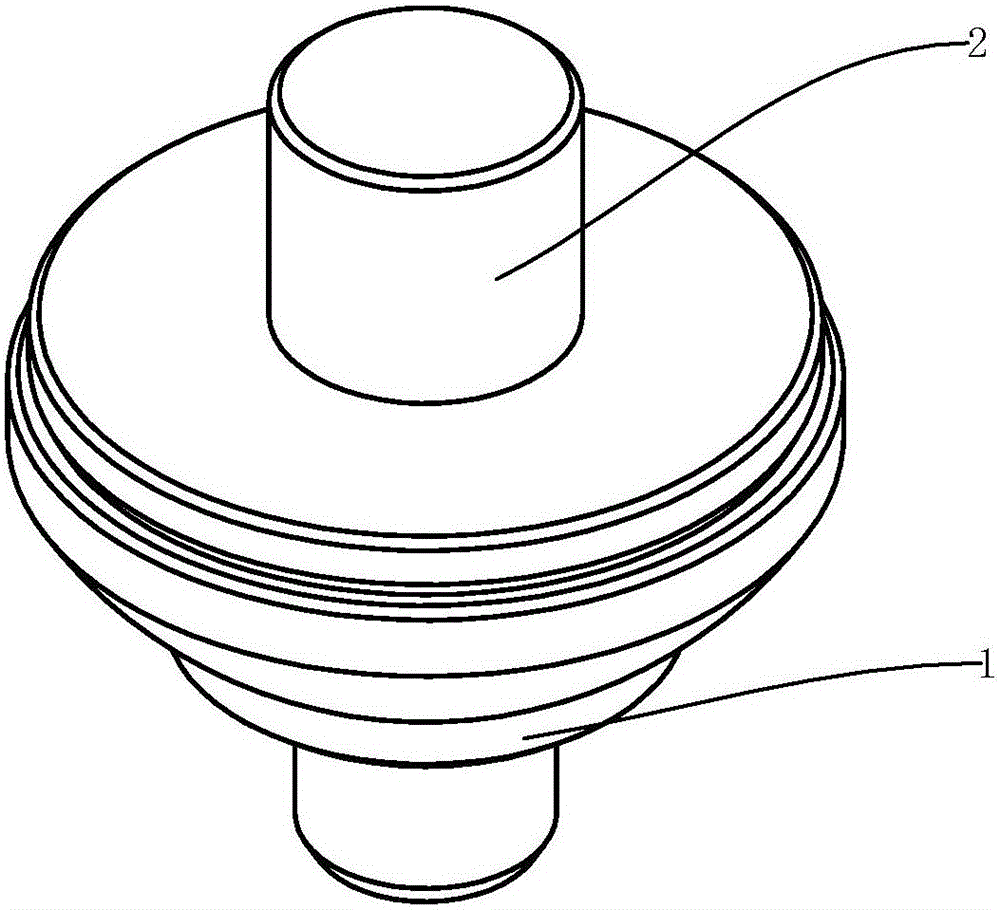
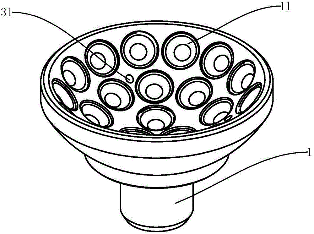
[0018] Such as figure 1 , figure 2 As shown, the drilling dish assembly of the present invention includes a drilling dish 1, on which at least one drilling dish counterbore 11 is arranged, and the drilling dish counterbore 11 is used for fixing the lens to be processed.

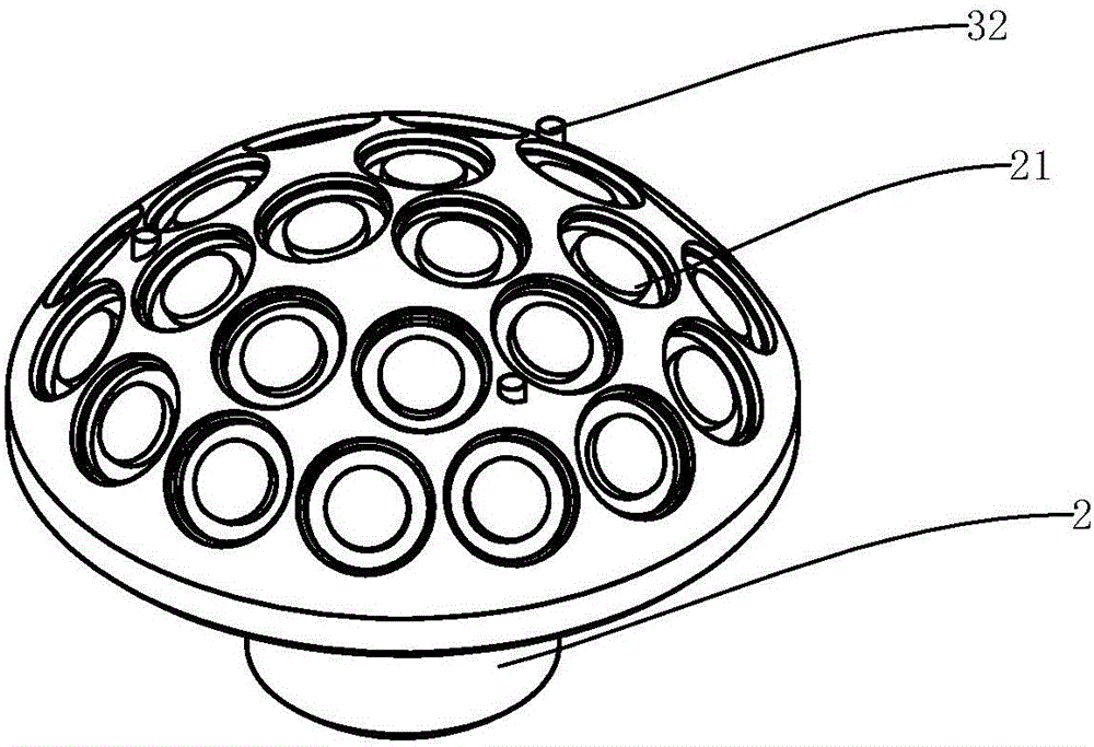
[0019] The improvements of this design are: Figure 3-Figure 5 As shown, the drilling dish assembly also includes an upper dish 2 for pressing the lens to be processed that is matched with the drilling dish 1, and the upper dish 2 that is matched with the drilling dish counterbore 11 is provided on the upper dish 2. Hole 21, the radius of curvature of the upper surface of the counterbore 21 of the upper dish is equal to the radius of curvature of the finished product on the surface of the lens to be processed, and the half angle of the counterbore 21 of the upper dish is equal to the half of the counterbore 11 at the corresponding position on the drilling dish Angle, the upper dish 2 is connected with the ...


PUM

PropertyMeasurementUnit
widthaaaaaaaaaa

Abstract

The invention discloses a drilling vessel assembly for an edge-thinned lens. The drilling vessel assembly comprises a drilling vessel, and the drilling vessel is provided with at least one drilling vessel counter bore used for fixing the lens. The drilling vessel assembly further comprises an upper disc vessel which is matched with the drilling vessel and used for compressing the lens to be processed. The upper disc vessel is provided with upper disc vessel counter bores matched with the drilling vessel counter bores. The upper disc vessel is connected with the drilling vessel through a locating piece. The upper disc vessel counter bores are provided with annular grooves, and silica gel sealing rings used for supporting the to-be-processed surface of the lens are arranged in the annular grooves. According to the drilling vessel assembly, when the lens is subjected to drilling vessel processing, the to-be-processed lens can be accurately positioned through the upper disc vessel and the drilling vessel, and the phenomena that the lens deflects on the drilling vessel and cannot be compressed completely due to thickness difference, and 'deflection' and non-uniform thickness happen to the processed lens can be avoided.

Description

technical field [0001] The invention relates to a lens drilling dish assembly, in particular to a thin edge lens drilling dish assembly. Background technique [0002] With the development of science and technology today, in the processing of optical glass spherical lenses, the thickness of the lens is getting thinner and thinner. For a lens with an edge width of less than 0.4mm (hereinafter referred to as a thin edge lens), it is processed by a drilling dish. At the same time, due to the thinner edge of the lens and the shallower depth of the edge of the counterbore of the drilling dish, the lens is easily shifted when it is placed on the drilling dish, so that it cannot be positioned reliably. Uniform bad phenomenon. Contents of the invention [0003] In order to solve the above technical problems, the object of the present invention is to provide a drilling dish assembly provided with an upper dish to press the lens. [0004] The technical scheme adopted in the present...

Claims


Application Information

Patent Timeline
Patent Type & Authority Applications(China)
IPC IPC(8): B28D1/14B28D7/04
CPCB28D1/143B28D7/04
Inventor 戈良辉阳咏梅郑德裕
Owner GUANGDONG KINGDING OPTICAL TECH CO LTD
Why Eureka
Try Eureka