A fan blade pre-embedded root flange device

A technology for fan blades and flanges, which is applied in the field of pre-embedded root flange devices for fan blades, can solve problems such as not easy to disassemble, affect positioning accuracy, and axial misalignment, and achieve improved stability and accuracy, large contact area, The effect of precise positioning

Active Publication Date: 2018-11-06
SINOMATECH WIND POWER BLADE +1
View PDF6 Cites 0 Cited by
  • Summary
  • Abstract
  • Description
  • Claims
  • Application Information

AI Technical Summary

Problems solved by technology

[0006] (1) In the prior art, the side connecting bolts and the foot connecting bolts are only fastened to the mold by passing through the circular holes on the upper half flange and the lower half flange, and in order to ensure the tightness of the root flange, The joint between the flange and the mold needs to be bonded with an adhesive material, which is easy to block the circular bolt holes. In addition, when the mold is demoulded, due to the use of round holes, when the flange is inclined relative to the vertical surface, it is not easy to easy to disassemble
[0007] (2) In the prior art, when realizing the connection of the root-end connecting bolts, it is necessary to set the positioning screw sleeve and the root-end connecting bolts on the upper half flange and the lower half flange for interference fit, and between the upper half mold and the lower half flange. The lower half of the mold is fixed with connecting screw sleeves, and the connecting bolts at the root end pass through the positioning screw sleeves and are fastened to the connecting screw sleeves, but the end faces of the positioning screw sleeves and the connecting screw sleeves are tapered surfaces, After long-term use, the blue will deform due to uneven force, resulting in inaccurate alignment and affecting positioning accuracy
[0008] (3) In the prior art, grooves are made on the upper half flange and the lower half flange, and then the positioning block is used for mold clamping and positioning, but the positioning block will be deformed after long-term use, resulting in the upper half flange and the lower half flange. The axial misalignment of the flange, and the locking structure fits the half flange, so that there is not enough space for adding adhesive materials when the upper and lower molds are closed.
[0009] (4) In order to ensure that the upper half flange and the lower half flange form a smooth and flat surface, it is necessary to adjust the axial positioning accuracy between the upper half flange and the lower half flange. Gaskets are added to the feet to achieve axial positioning adjustment. However, during the process of loosening the bolts on the iron feet and inserting the gaskets, it is likely that the bolts will be deformed and misplaced due to the gravity of the half-flange, making the upper half-flange and the lower half-flange. The half-flange is misaligned in the longitudinal direction or flipped so that the entire flange surface is no longer complete

Method used


Image

  • A fan blade pre-embedded root flange device
  • A fan blade pre-embedded root flange device
  • A fan blade pre-embedded root flange device

Examples


Embodiment Construction

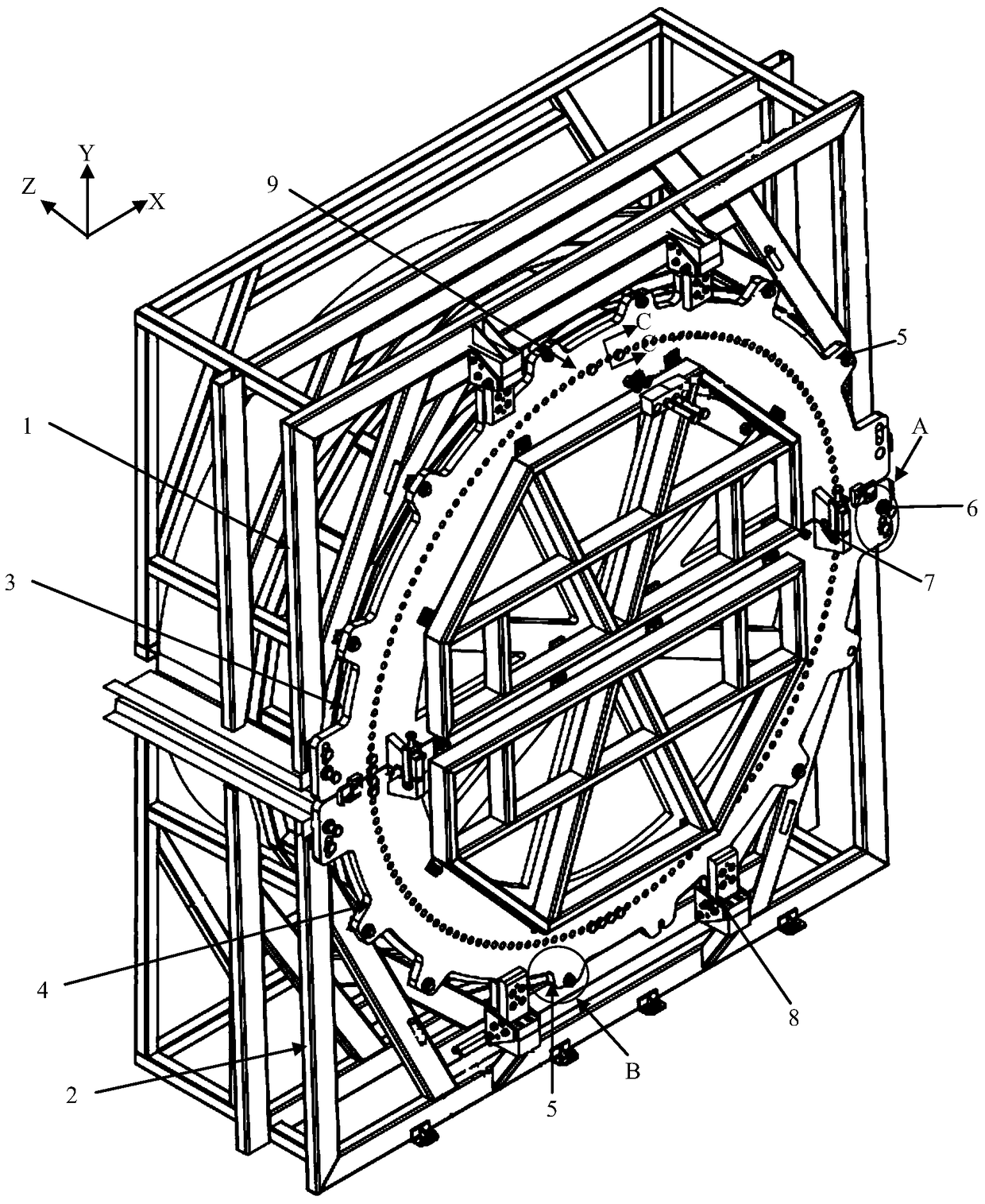
[0036] In the following description, the Y-axis direction is taken as the longitudinal direction, the Z-axis direction is taken as the axial direction, and the X-axis direction is taken as the transverse direction.

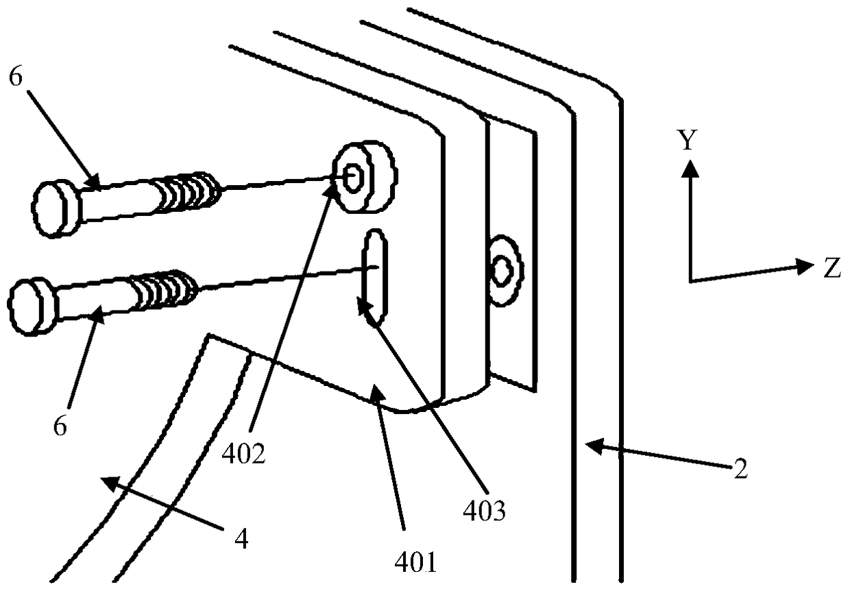
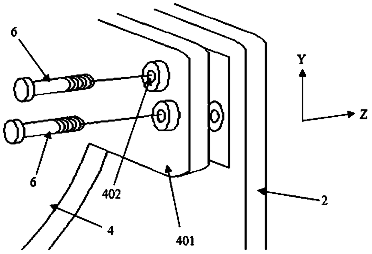
[0037] refer to figure 1 , the pre-embedded root flange device of the fan blade in this embodiment includes: an upper half flange 3, a lower half flange 4, an upper half mold 1 and a lower half mold 2, and the upper half flange 3 is connected by an iron foot 8, a side Bolts 6, foot connecting bolts 5 and root-end connecting bolts 9 are installed on the upper half-mold 1. Similarly, the lower half-flange 4 is installed on the lower half-mold 2 through iron feet 8, side connecting bolts 5 and root-end connecting bolts 9. superior. That is to say, the installation structure of the upper half flange 3 and the upper half mold 1 is basically the same as the installation structure of the lower half flange 4 and the lower half mold 2, so in the following description, the...


PUM


Abstract

The invention provides an embedded root flange device for a fan blade. The device comprises an upper half flange, a lower half flange, an upper half mold and a lower half mold, wherein the upper half flange is mounted on the upper half mold by the aid of iron feet, side connecting bolts, bottom foot connecting bolts and root end connecting bolts, the lower half flange is mounted on the lower half mold by the aid of iron feet, side connecting bolts and root end connecting bolts, and after the upper half mold and the lower half mold are closed, the upper half flange and the lower half flange are locked by locking devices to form a complete root flange; first round holes and first kidney-shaped holes are pairwise formed in the upper half flange and the lower half flange, one side connecting bolt penetrates through one first round hole, and the other side connecting bolt penetrates through one first kidney-shaped hole. The device has the advantages of high positioning precision and convenience in dismounting.

Description

technical field [0001] The invention relates to the field of wind power generators, in particular to a fan blade pre-embedded root flange device. Background technique [0002] At present, in the wind power industry, the mainstream technologies for blade root structure design are generally divided into two types: post-drilling technology and pre-embedding technology. [0003] The post-punching process is to leave a certain length of margin at the root of the blade when the glass fiber is laid during the blade manufacturing process. After the blade is molded and demoulded, the margin is cut off with a punching machine to obtain a more perfect plane. , and then drill holes through axial and radial positioning, and install round nuts and stud bolts inside. When the blade is installed, connect and fix the other end of the stud bolt to the hub of the wind turbine; [0004] The pre-embedding process is to pre-place the pre-embedded bolt sleeve with internal thread in the middle o...

Claims


Application Information

Patent Timeline
Patent Type & Authority Patents(China)
IPC IPC(8): B29C33/20
Inventor 李辉颜晨王晓明陈淳张存义
Owner SINOMATECH WIND POWER BLADE
Why Eureka
Try Eureka