Movable roof device

A movable and roof technology, applied in the direction of roof, roof, roof cladding, etc., can solve the problems of inability to open the roof for ventilation, inflexible use, and small opening and closing range, so as to save complicated procedures, facilitate construction, Open and close flexible effect

Active Publication Date: 2016-07-20
GUANGDONG DEBOX CONSTR TECH CO LTD
View PDF9 Cites 2 Cited by
  • Summary
  • Abstract
  • Description
  • Claims
  • Application Information

AI Technical Summary

Problems solved by technology

[0002] In the existing sun room, greenhouse and other buildings, there are roughly two types of roof structures: one is that the roof is fixed and cannot be opened and closed, so that the roof cannot be opened for ventilation during application. Ventilation, and direct sunlight into the house to sterilize the interior space
The other is that the roof can be opened and closed, but the opening and closing is carried out by moving the wall connected to the roof. This opening and closing method needs to occupy a certain space in the process of extending and closing to complete the opening and closing. Moreover, this opening and closing method is a large-scale, large-area opening and closing, the opening and closing range that users can choose is very small, and it is not flexible enough to use

Method used


Image

  • Movable roof device
  • Movable roof device
  • Movable roof device

Examples


Embodiment Construction

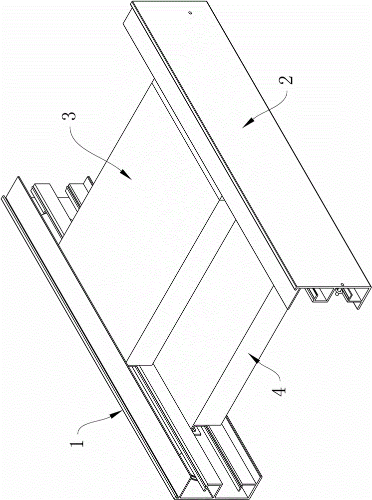
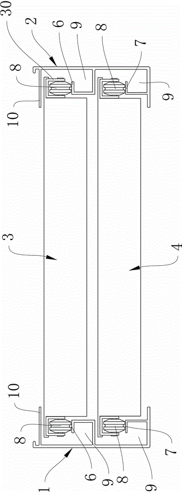
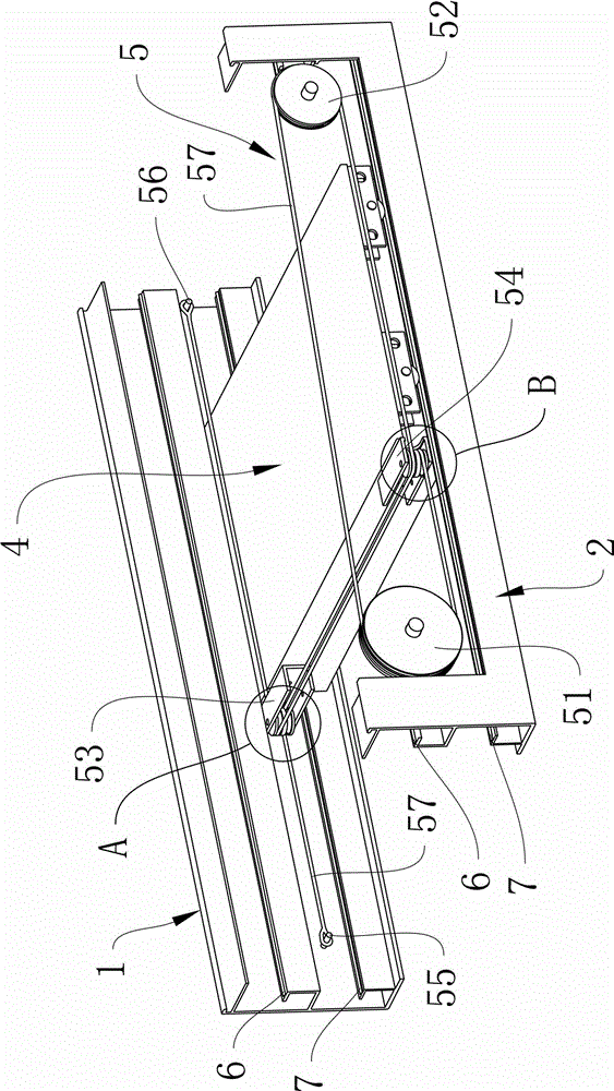
[0016] Such as figure 1 , figure 2 , image 3 As shown, a movable roof device described in the utility model includes a left beam body 1, a right beam body 2, an upper roof 3, a lower roof 4, and a driving mechanism 5, wherein

[0017] Said upper floor roof 3 and lower floor roof 4 are respectively installed between the left beam body 1 and the right beam body 2 according to the structural arrangement of the upper floor and the lower floor, and the two sides of the upper floor roof 3 are connected with the left beam body 1 and the right beam body 2 respectively. Slidingly connected, the two sides of the lower roof 4 are respectively connected to the left beam body 1 and the right beam body 2 in a sliding phase. That is to say, the upper roof 3 and the lower roof 4 can guide and slide along the left beam body 1 and the right beam body 2 .

[0018] The driving mechanism 5 is arranged between the left beam body 1 and the right beam body 2, and the driving mechanism 5 is conne...


PUM


Abstract

The invention relates to a movable roof device which is characterized by comprising a left beam body, a right beam body, an upper layer top plate, a lower layer top plate and a drive mechanism, wherein the upper layer top plate and the lower layer top plate are installed between the left beam body and the right beam body respectively according to structural layout of an upper layer and a lower layer; two side edges of the upper layer top plate are in a sliding connection with the left beam body and the right beam body respectively; two side edges of the lower layer top plate are in a sliding connection with the left beam body and the right beam body respectively; the drive mechanism is arranged between the left beam body and the right beam body; and the drive mechanism is in a transmission connection with the upper layer top plate and the lower layer top plate, so that the upper layer top plate and the lower layer top plate can be driven to be unfolded or overlap together. The movable roof device has the advantages that the structure is simple; opening and closing are flexible; use is convenient; space occupation is avoided during the opening and closing; and a user can flexibly choose an orientation for the opening and closing according to demands.

Description

technical field [0001] The utility model relates to the field of sunshine houses, in particular to a movable roof device applied to the sunshine house. Background technique [0002] In the existing sun room, greenhouse and other buildings, there are roughly two types of roof structures: one is that the roof is fixed and cannot be opened and closed, so that the roof cannot be opened for ventilation during application. Ventilation, and direct sunlight into the house to sterilize the interior space. The other is that the roof can be opened and closed, but the opening and closing is carried out by moving the wall connected to the roof. This opening and closing method needs to occupy a certain space in the process of extending and closing to complete the opening and closing. Moreover, this opening and closing method is a large-scale, large-area opening and closing, and the opening and closing range that users can choose is very small, and it is not flexible enough to use. Based...

Claims


Application Information

Patent Timeline
Patent Type & Authority Applications(China)
IPC IPC(8): E04B7/16E04D13/064
Inventor 吴志勇
Owner GUANGDONG DEBOX CONSTR TECH CO LTD
Why Eureka
Try Eureka