Novel movable fence
A new type of fence technology, applied in the direction of fences, building types, roads, etc., can solve the problems of large space required for transportation and collection, waste of resources, and large volume of isolation equipment, so as to reduce traffic accident injuries, reduce resource waste, and reduce the scope of application. wide effect
- Summary
- Abstract
- Description
- Claims
- Application Information
AI Technical Summary
Problems solved by technology
Method used
Image
Examples
Embodiment 1
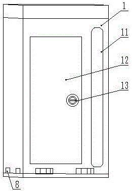
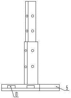
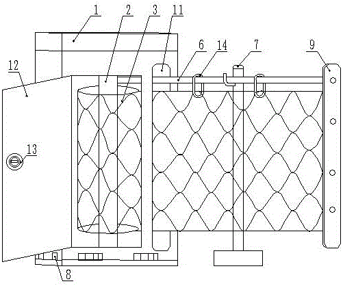
[0038] Such as Figure 1~4 Shown, a kind of novel motorized isolation fence, it comprises casing 1, rotating shaft 2, fence 3, main support column 5, auxiliary support column 7 and support cable 6.
[0039] Such as Figure 7 As shown, the upper and lower ends of the rotating shaft 2 are rotatably installed inside the box body 1 through bearings respectively, and the rotating shaft 2 is connected with a driving mechanism 4 for driving the rotating shaft 2 to rotate. The driving mechanism 4 is a rotating motor, and the rotating motor It is also arranged inside the box body 1. One end of the fence 3 is detachably arranged on the rotating shaft 2 , and the other end of the fence 3 can protrude from the fence outlet 11 on the box body 1 . In addition, one side of the box body 1 is also provided with a box door 12, and the box door 12 is provided with a lock body 13, and the inside of the box body 1 is provided with a locking structure, which can be locked when the fence 3 is fold...
Embodiment 2
[0043] The difference between this embodiment and Embodiment 1 is that: the inside of the box 1 is provided with a special support cable winding mechanism, the deployment and retraction of the support cable 6 can be controlled separately, and the box 1 is provided with a special support Cable exit 10. During use, the support cable 6 can be pulled out from the support cable outlet 10 earlier, be fixed on the main support column 5 at the far end, then expand the fence 3, be fixed on the main support column 5, and use the auxiliary support column 7 Support support cable 6, its use status is as Figure 8shown.
Embodiment 3
[0045] The difference between this embodiment and Embodiment 2 is that: the four sides of the box body 1 are respectively provided with a support cable outlet 10 and a fence outlet 11, so that the fence 3 can be pulled out from different directions. The structure of the box body 1 is as follows: Figure 9 shown.
PUM
 Abstract
Description
Claims
Application Information
 - R&D
- Intellectual Property
- Life Sciences
- Materials
- Tech Scout
- Unparalleled Data Quality
- Higher Quality Content
- 60% Fewer Hallucinations
Browse by: Latest US Patents, China's latest patents, Technical Efficacy Thesaurus, Application Domain, Technology Topic, Popular Technical Reports.
© 2025 PatSnap. All rights reserved.Legal|Privacy policy|Modern Slavery Act Transparency Statement|Sitemap|About US| Contact US: help@patsnap.com


