
Hook ladder for cable repairing

A technology for hanging ladders and cables, which is applied to overhead lines/cable equipment, ladders, buildings, etc., which can solve the problems of casualties, easy decoupling, etc., and achieve the effect of convenient maintenance and increased friction

Inactive Publication Date: 2016-07-20
CHENGDU KELIFU SCI & TECH
View PDF5 Cites 3 Cited by
  • Summary
  • Abstract
  • Description
  • Claims
  • Application Information

AI Technical Summary

Problems solved by technology

[0003] The purpose of the present invention is to overcome the shortcomings and deficiencies of the above-mentioned prior art, and provide a hanging ladder for cable repair, which solves the problem that the existing hanging ladder is prone to decoupling when the cable is shaken during use, which may cause casualties.

Method used


Image

  • Hook ladder for cable repairing
  • Hook ladder for cable repairing
  • Hook ladder for cable repairing

Examples


Embodiment 1

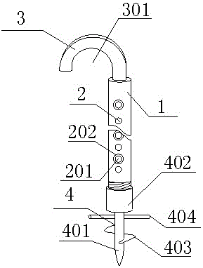
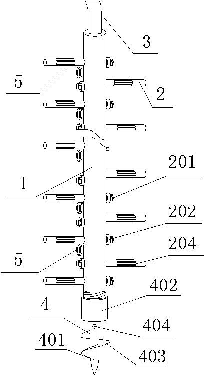
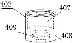
[0022] like figure 1 , figure 2 , Figure 5 As shown in the figure, a cable repair hanging ladder includes a cylindrical rod body 1, a plurality of legs 2 arranged on the peripheral wall of the rod body 1, a hook 3 arranged on the upper end of the rod body 1, and a fixer arranged on the lower end of the rod body 1. 4. The fixer 4 includes a fixed rod 401 and a screw joint 402. The screw joint 402 is a cylinder, one end of which is rotatably connected to the upper end of the fixed rod 401, and the other end is threadedly connected to the lower end of the rod body 1. The screw joint 402 and the fixing rod 401 can rotate mutually in the circumferential direction, but cannot move in the axial direction. The lower end of the fixing rod 401 is a pointed tip, and the peripheral wall is spirally surrounded by a blocking blade 403, and the supporting feet 2 are all vertical. In the rod body 1, the legs 2 are divided into two rows, and the arrangement direction is along the extension...

Embodiment 2

[0026] like Image 6 , the structure of this embodiment is basically the same as that of Embodiment 1, the difference is that the groove 301 of the hook 3 is provided with a groove 302, the groove wall of the groove 302 is covered with bumps 303, and the hook 3 is hooked on the cable , the cable will be located in the groove 302, and the convex point 303 is set in the groove 302, so that the cable will not be easily disengaged from the hook 3

Embodiment 3

[0028] like Figure 7 , the structure of this embodiment is basically the same as that of the second embodiment, the difference is that the fixed rod 401 is provided with a helical groove 405 whose helical direction is the same as that of the blocking blade 403 . The fixing rod 401 is screwed into the ground, and a helical groove 405 is provided to make it more convenient for the fixing rod 401 to enter the ground.


PUM


Abstract

The invention discloses a hook ladder for cable repairing.The hook ladder for cable repairing comprises a cylindrical rod body, multiple supporting feet arranged on the peripheral wall of the rod body, a hook arranged at the upper end of the rod body and a fixator arranged at the lower end of the rod body, wherein the supporting feet are in threaded connection with the rod body through threaded ends, a circumferential groove is formed in each supporting foot, and a matched rubber sleeve is arranged in the circumferential groove.The hook ladder has the advantages that one rubber sleeve is arranged on each supporting foot in the hook ladder, convex strips are further arranged on each rubber sleeve to increase a friction force between shoe soles and the supporting feet, and a slip phenomenon rarely occurs during climbing, the supporting feet are in threaded connection with the rod body, and the ladder can be used again by mounting one new supporting foot after one supporting foot is damaged, so that repair is very convenient.

Description

technical field [0001] The invention relates to a climbing ladder, in particular to a cable repair hanging ladder. Background technique [0002] At present, in the power system, the hanging ladder used to detect cables generally includes a rod body, a hook, and a foot. When in use, the hook is hung on the cable, and the staff climbs on the bracket, but when the staff climbs, the Some legs are generally round rods. When the staff climbs, it is very easy to slip. Although there will be safety ropes hanging on the ladder, there will be no danger to life, but the staff will still be knocked on the legs. , resulting in injury, and it will take a lot of effort to return to the hanging ladder, which brings great inconvenience to the staff. Moreover, the legs of the existing hanging ladder are welded on the rod body, which requires a lot of support when climbing. When repairing, it is necessary to take the ladder to the repair shop, and then weld a new leg, but this is very trouble...

Claims


Application Information

Patent Timeline
Patent Type & Authority Applications(China)
IPC IPC(8): E06C1/36E06C7/08E06C7/50E06C7/42H02G1/02
CPCE06C1/36E06C7/081E06C7/082E06C7/42E06C7/50H02G1/02
Inventor 胡明容
Owner CHENGDU KELIFU SCI & TECH
Learn More