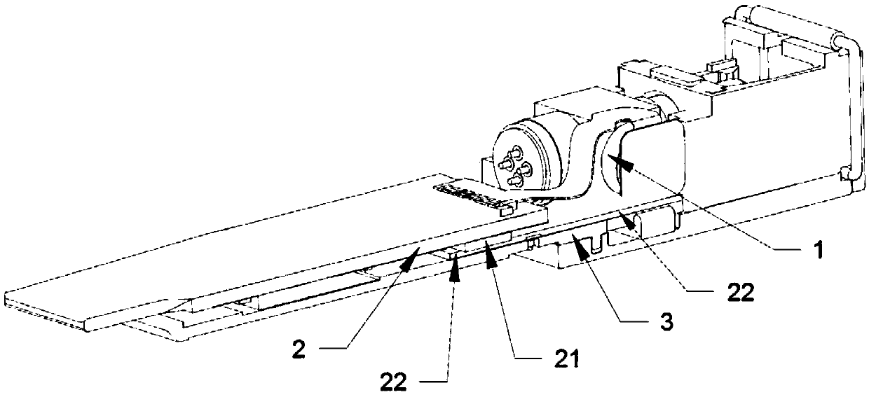
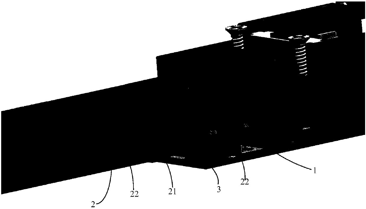
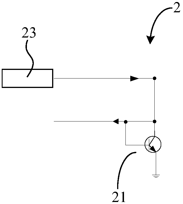
an optical module

An optical module and monitoring module technology, applied in the field of optical modules, can solve problems such as affecting laser performance, inaccurate detection temperature, and difficulty in achieving accurate laser temperature monitoring, so as to overcome inaccurate temperature monitoring, avoid temperature changes, and improve stability. Effect

Active Publication Date: 2019-06-14
HISENSE BROADBAND MULTIMEDIA TECH
View PDF9 Cites 0 Cited by
  • Summary
  • Abstract
  • Description
  • Claims
  • Application Information

AI Technical Summary

Problems solved by technology

[0003] In the prior art, a chip with a temperature sensor is usually used to detect the temperature of the environment inside the optical module, and the temperature of the laser is calculated on the basis of increasing the compensation value. This way of detecting the temperature is not accurate, and it is difficult to realize the temperature of the laser. Accurate monitoring of the temperature of the laser, which in turn affects the performance of the laser

Method used


Image

  • an optical module
  • an optical module
  • an optical module

Examples


Embodiment Construction

[0019] The technical solutions in the embodiments of the present invention will be clearly and completely described below in conjunction with the accompanying drawings in the embodiments of the present invention. Obviously, the described embodiments are only a part of the embodiments of the present invention, rather than all the embodiments. Based on the embodiments of the present invention, all other embodiments obtained by those of ordinary skill in the art without creative work shall fall within the protection scope of the present invention.

[0020] In the description of the present invention, it should be understood that the terms "center", "upper", "lower", "front", "rear", "left", "right", "vertical", "horizontal", The orientation or positional relationship indicated by "top", "bottom", "inner", "outer", etc. are based on the orientation or positional relationship shown in the drawings, and are only for the convenience of describing the present invention and simplifying the...


PUM


Abstract

The invention relates to the technical field of communications, in particular to an optical module. The monitoring accuracy of the laser temperature is improved, and the performance of the laser is improved. It overcomes the defect in the prior art that the temperature monitoring of the laser is inaccurate, which reduces the performance of the optical component. An embodiment of the present invention provides an optical module, including: an optical component and a temperature monitoring module, wherein a laser is packaged in the optical component; the temperature monitoring module includes: a temperature measuring element, and the temperature measuring component passes through The heat conduction part is connected, the heat conduction part is used to conduct the heat emitted by the laser to the temperature measuring element, and the temperature monitoring module is used to adjust the driving current of the laser according to the temperature detected by the temperature measuring element, so that the driving current of the laser corresponds to the detected temperature The optical power current of the laser is matched. The embodiments of the present invention are applied to the production and manufacture of optical modules.

Description

Technical field [0001] The present invention relates to the field of communication technology, in particular to an optical module. Background technique [0002] In the optical module, temperature has a great influence on the characteristics of the laser, because the optical power current of the laser changes with the temperature of the laser, and the driving current of the laser needs to be the same as the optical power current of the laser. To ensure that the laser can output the required output signal, the temperature of the laser is monitored to control the driving current of the laser, so that the driving current of the laser corresponds to the light of the laser corresponding to the temperature. The power and current are matched to improve the stability of the laser output signal. [0003] In the prior art, a chip with a temperature sensor is usually used to detect the temperature of the environment in the optical module, and the temperature of the laser is calculated on the ...

Claims


Application Information

Patent Timeline
Patent Type & Authority Patents(China)
IPC IPC(8): G01K13/00
CPCG01K13/00
Inventor 高修东陈福军
Owner HISENSE BROADBAND MULTIMEDIA TECH
Why Eureka
Try Eureka