
A rotary automatic reversing switch

An automatic reversing and rotating technology, applied in the direction of electric switches, electrical components, circuits, etc., can solve problems such as poor contact, low efficiency, and easy failures, and achieve high stability, large capacity, and low loss.

Inactive Publication Date: 2018-06-08
绍兴市承天电器有限公司
View PDF4 Cites 0 Cited by
  • Summary
  • Abstract
  • Description
  • Claims
  • Application Information

AI Technical Summary

Problems solved by technology

[0002] The existing commutation method, low power uses relay commutation, high power uses manual switch or thyristor electronic commutation, the power of relay commutation is not large, the maximum current is generally below 200 amperes and the relay is unstable It is prone to failure; it is troublesome to change the direction with manual switch blades. Each time the direction is changed, it needs to be changed manually. Every time the direction is changed, electric sparks will be generated, which is easy to burn the switch blades. Over time, it is prone to poor contact and automatic change cannot be realized. The commutation efficiency is not high with silicon controlled rectifiers, and the heat generation is large. The electronic devices are relatively fragile, and the parallel connection is more unreliable and stable.

Method used


Image

  • A rotary automatic reversing switch
  • A rotary automatic reversing switch
  • A rotary automatic reversing switch

Examples


Embodiment

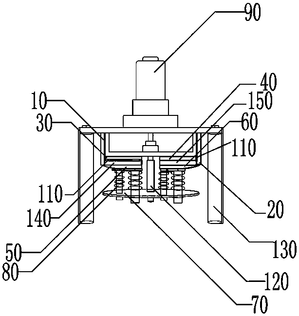
[0023] A rotary automatic reversing switch, (such as figure 1 (shown) includes a bracket 130, and a motor 90 is arranged on the bracket 130, and the motor 90 is used to drive the rotating disk to rotate, and a DC motor can be used for forward and reverse rotation.

[0024] The first output electrode 30 and the second output electrode 40 are sequentially arranged on the support 130 , and the first output electrode 30 and the second output electrode 40 are located on both sides of the center of the support 130 .

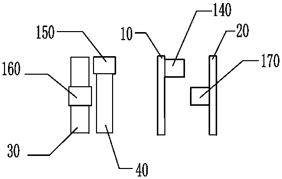
[0025] The first output electrode 30 is provided with a third terminal 160 (which can be connected by screws, the same below), and the second output electrode 40 is provided with a second terminal 150, (such as figure 2 shown on the left).

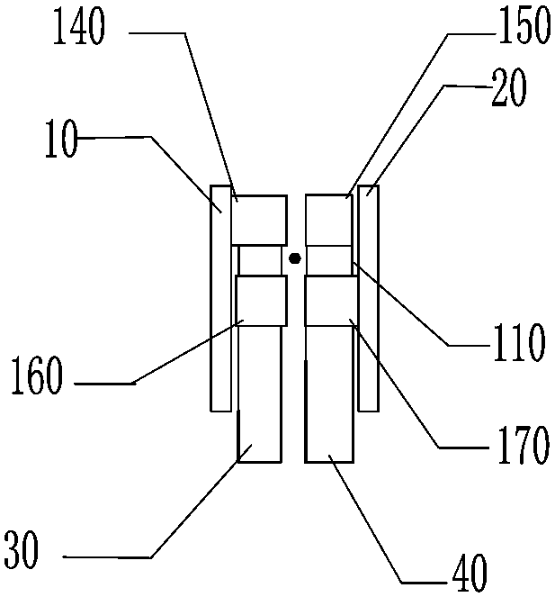
[0026] The first terminal 140 is installed on the first output electrode 30 through the insulating plate 110, the fourth terminal 170 is installed on the second output electrode 40 through the insulating plate 110, the first term...


PUM


Abstract

The invention provides a rotary automatic reversing switch, which includes a bracket, a first output electrode and a second output electrode are arranged on the bracket, a third terminal is arranged on the first output electrode, and a third terminal is arranged on the second output electrode. A second terminal is arranged on the first output electrode, a first terminal is installed on the first output electrode through an insulating plate, a fourth terminal is installed on the second output electrode through an insulating plate, and a second terminal is arranged on the left side of the first terminal. An input electrode, the right side of the fourth terminal is provided with a second input electrode; the center of the bracket is provided with a rotating shaft, one end of the rotating shaft is connected to a rotating disc, and a number of springs are fixedly connected above the rotating disc, and the ends of the springs Install the first rotating electrode and the second rotating electrode. The invention has the characteristics of high efficiency, low loss, large capacity, small volume and high stable performance.

Description

technical field [0001] The invention belongs to the technical field of a rectifying electroplating power reversing device, in particular to a rotary automatic reversing switch. Background technique [0002] The existing commutation method, low power uses relay commutation, high power uses manual switch or thyristor electronic commutation, the power of relay commutation is not large, the maximum current is generally below 200 amperes and the relay is unstable It is prone to failure; it is troublesome to change the direction with manual switch blades. Each time the direction is changed, it needs to be changed manually. Every time the direction is changed, electric sparks will be generated, which is easy to burn the switch blades. Over time, it is prone to poor contact and automatic change cannot be realized. The commutation efficiency of silicon controlled rectifiers is not high, and electronic devices with high heat generation are relatively fragile and parallel connections a...

Claims


Application Information

Patent Timeline
Patent Type & Authority Patents(China)
IPC IPC(8): H01H19/08H01H19/10
CPCH01H19/08H01H19/10
Inventor 倪宏亮罗小兵李长春
Owner 绍兴市承天电器有限公司
Learn More