Automatic adjustment method and system for cavity filter
A cavity filter and automatic adjustment technology, which is applied to waveguide devices, electrical components, circuits, etc., can solve the problems of poor generalization and stability, and can not achieve fine waveform adjustment, etc., to achieve strong generalization and stability Effect
- Summary
- Abstract
- Description
- Claims
- Application Information
AI Technical Summary
Problems solved by technology
Method used
Image

Examples
Embodiment 1
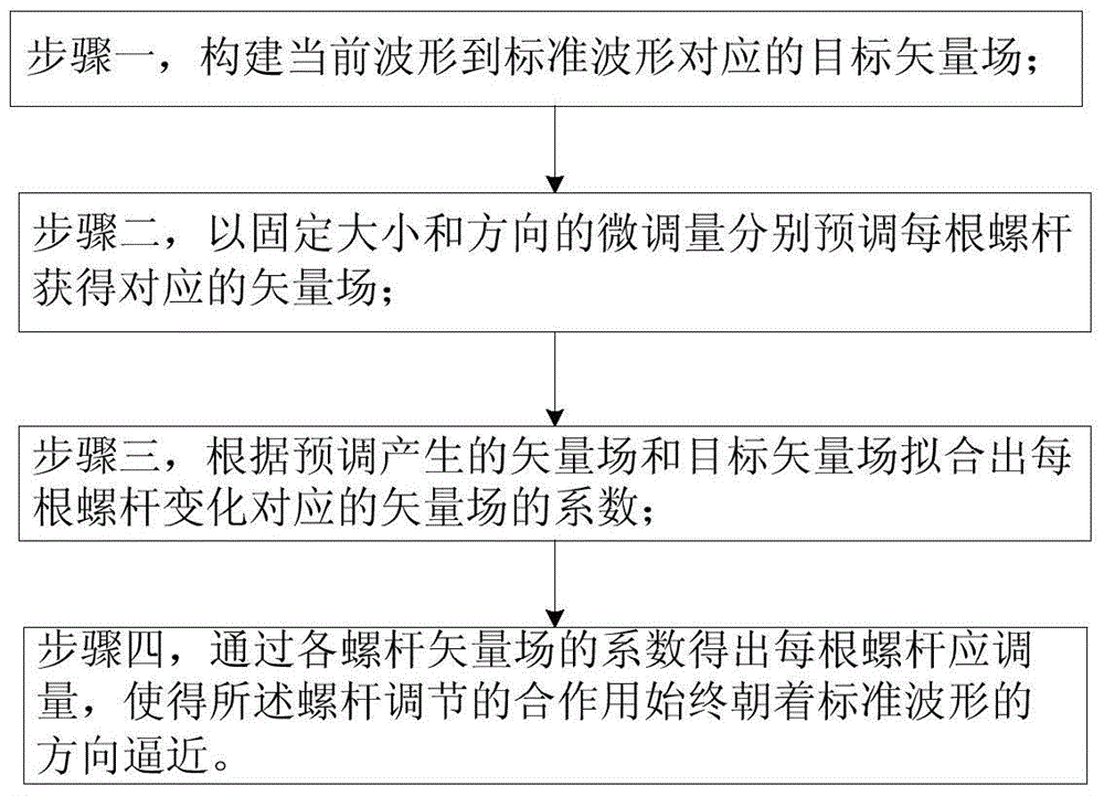
[0021] Embodiment one, such as figure 1 As shown, a cavity filter automatic adjustment method, the technical solution includes:
[0022] Step 1: Construct the target vector field corresponding to the current waveform to the standard waveform;
[0023] Modeling from the mathematical point of view of vector field, using vector field to describe the change direction of arbitrary waveform shape; the expression of vector field in this technical solution includes but not limited to the way of describing the change with straight lines, curves, or similar methods described by other mathematical names .
[0024] Step 2: Pre-adjust each screw to obtain the corresponding vector field with the fine-tuning amount of fixed size and direction;
[0025] Each screw is pre-adjusted and then reset, and the vector field generated when each screw is fine-tuned is collected. The main purpose of this step is to collect the vector field represented by each screw in the current state. The technica...
Embodiment 2
[0030] Embodiment two, such as Figures 2 to 4 As shown, on the basis of Embodiment 1, more preferably, the vector field is used to describe the trend of the waveform change caused by the adjustment of the screw, that is, evenly sample discrete points on the two waveforms before and after the change, and make a point Correspondence is a method of connecting corresponding points to show the trend of change.
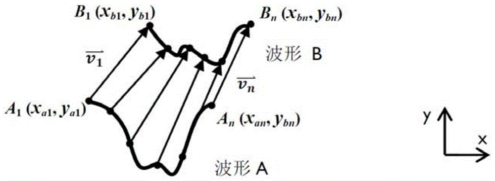
[0031] Such as figure 2 As shown, waveform A and waveform B are two different adjustment states. If the same number of points are uniformly and discretely sampled on waveforms A and B, then the process of changing waveform A to waveform B can use the vector field (or called Vector field, English: vectorfield) to represent.
[0032] Establish a two-dimensional Cartesian coordinate system, the horizontal axis is the x-axis, and the vertical axis is y. Then according to the description above, a certain point A on the waveform A j (x aj ,y aj ) to a point B on the wave...
Embodiment 3
[0073] Embodiment three, such as Figure 5 As shown, a cavity filter automatic adjustment system, the technical solution includes four parts: an actuator, a control mechanism, a filter to be adjusted, and a vector network analyzer, and the four parts are connected in a closed loop.
[0074] More preferably, the actuator is controlled by a control mechanism to rotate or loosen the screw or nut on the filter to be adjusted.
[0075] More preferably, the control mechanism includes: a human-computer interaction interface, a motion control card, and a data acquisition card, the human-computer interaction interface has the function of running a vector field method or other automatic adjustment algorithms; The actuator has the function of motion control; the data acquisition card has the function of communicating with the vector network analyzer and acquiring and storing waveform data.
[0076] The filter to be adjusted generally refers to various filter products applicable to the tec...
PUM
 Abstract
Description
Claims
Application Information
 - Generate Ideas
- Intellectual Property
- Life Sciences
- Materials
- Tech Scout
- Unparalleled Data Quality
- Higher Quality Content
- 60% Fewer Hallucinations
Browse by: Latest US Patents, China's latest patents, Technical Efficacy Thesaurus, Application Domain, Technology Topic, Popular Technical Reports.
© 2025 PatSnap. All rights reserved.Legal|Privacy policy|Modern Slavery Act Transparency Statement|Sitemap|About US| Contact US: help@patsnap.com