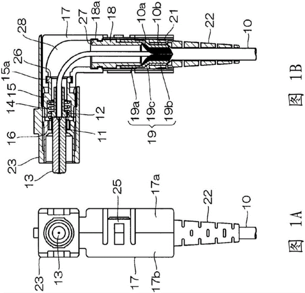
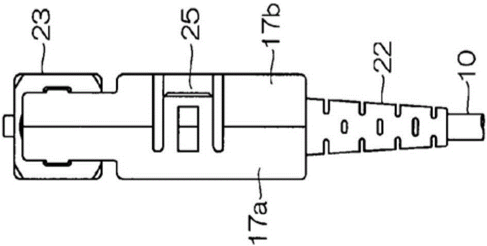
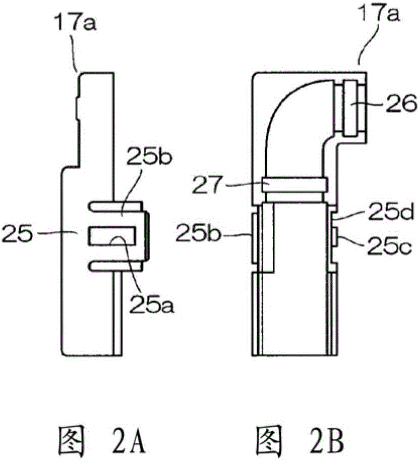
L-angle type optical connector
An optical connector and angle-shaped technology, which is applied in light guides, optics, instruments, etc., can solve the problem of increasing the number of parts and achieve the effect of reducing the number of parts and the number of assembly processes
- Summary
- Abstract
- Description
- Claims
- Application Information
AI Technical Summary
Problems solved by technology
Method used
Image
Examples
Embodiment Construction
[0027] Hereinafter, examples of the present invention will be described.
[0028] Figures 4A-4C Showing the appearance of an embodiment of the L-angle optical connector of the present invention, Figure 5A , 5B Indicates its cross-sectional structure. In this example, the L-angle optical connector is composed of a housing 30 , an L-angle member 40 , a ferrule 50 , a coil spring 60 , a sleeve 70 , a riveting ring 80 , a screw 90 and a protective cover 100 . In addition, in Figures 4A-4C and Figure 5A , 5B Among them, 200 represents the optical cable.
[0029] First, the configuration of each unit will be described.
[0030] Housing 30 such as Figures 6A-6F As shown, it is composed of a cylindrical portion 31 , a square flange portion 32 provided at the rear end of the cylindrical portion 31 , and an extension portion 33 formed to extend rearward from the flange portion 32 . The four corners of the flange part 32 are chamfered, and the holes 32a for mounting and fix...
PUM
 Abstract
Description
Claims
Application Information
 - R&D
- Intellectual Property
- Life Sciences
- Materials
- Tech Scout
- Unparalleled Data Quality
- Higher Quality Content
- 60% Fewer Hallucinations
Browse by: Latest US Patents, China's latest patents, Technical Efficacy Thesaurus, Application Domain, Technology Topic, Popular Technical Reports.
© 2025 PatSnap. All rights reserved.Legal|Privacy policy|Modern Slavery Act Transparency Statement|Sitemap|About US| Contact US: help@patsnap.com


