A kind of automatic material rod unloading equipment

An automatic, rod-based technology, applied in the direction of ejection equipment, metal processing equipment, feeding devices, etc., can solve the problems of protection treatment of material section, affecting the quality of material section, and oxidation of cutting surface, so as to improve work efficiency and improve downtime. The effect of material quality

Inactive Publication Date: 2017-08-18
JIANGSU TIANGANG PRECISION CASTING CO LTD
View PDF9 Cites 0 Cited by
  • Summary
  • Abstract
  • Description
  • Claims
  • Application Information

AI Technical Summary

Problems solved by technology

For blanking packaging, after the material is processed by the operation table, it needs to be blanked. At this time, it is necessary to use the blanking equipment. At present, in the blanking process of industrial production in many industries, the blanking equipment often only divides the material rod. There are multiple material sections with a predetermined length, and the section of the material section is not protected, which will cause oxidation of the cutting surface of each material section after blanking, which will affect the quality of the material section

Method used


Image

  • A kind of automatic material rod unloading equipment
  • A kind of automatic material rod unloading equipment
  • A kind of automatic material rod unloading equipment

Examples


Embodiment Construction

[0025] In order to make the content of the present invention clearer and easier to understand, the content of the present invention will be described in detail below in conjunction with specific embodiments and accompanying drawings.

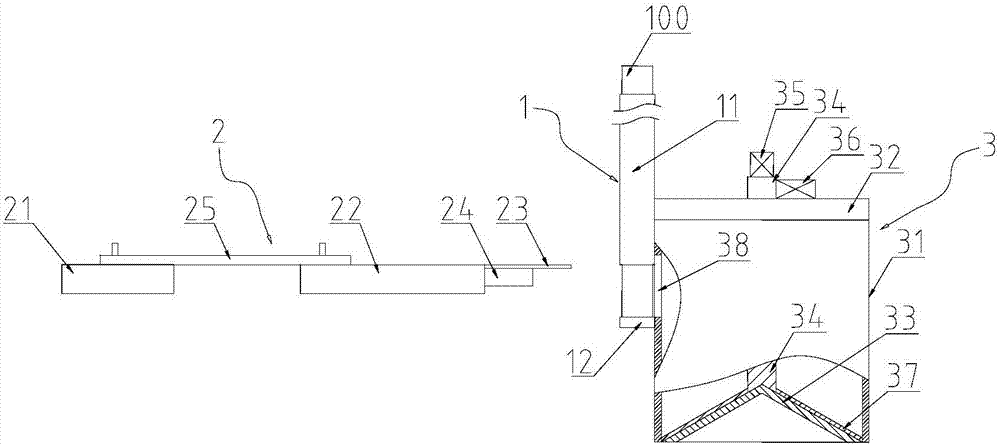
[0026] refer to figure 1 , figure 1 A schematic structural view of an automatic rod blanking device according to an embodiment of the present invention is schematically shown.

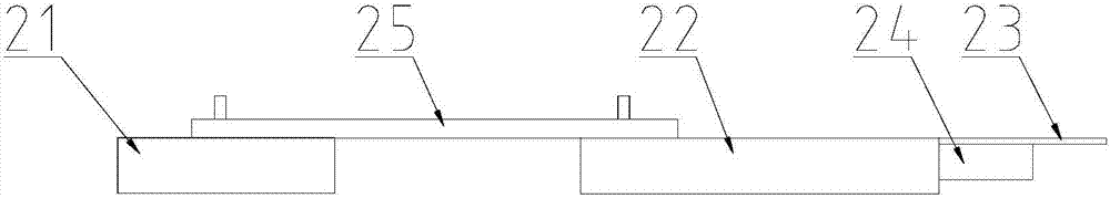
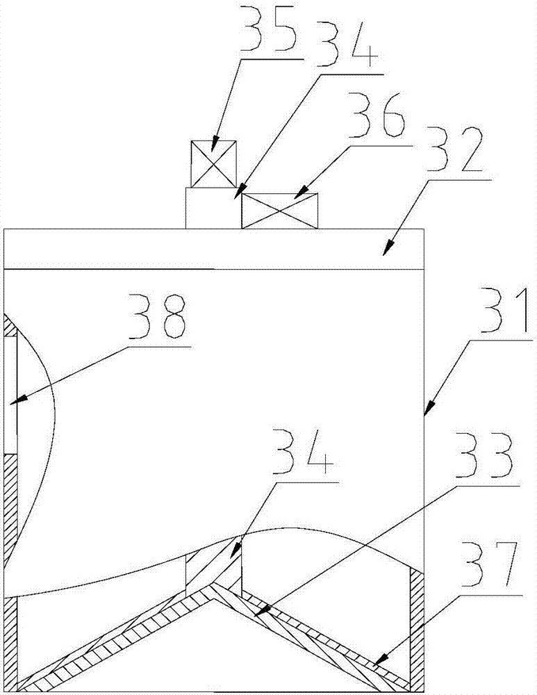
[0027] The automatic rod blanking equipment of this embodiment includes: a feeding mechanism 1, a blanking mechanism 2 and a discharging mechanism 3, through the cooperation of the feeding mechanism 1, the blanking mechanism 2 and the discharging mechanism 3, automatic feeding, Unloading and discharging greatly improves the working efficiency of the unloading equipment.

[0028] The feeding mechanism 1 is used to convey the material rod 100, and the feeding mechanism 1 includes: a material guide tube 11 for accommodating the material rod 100 and a material limiting pla...


PUM


Abstract

The invention discloses automatic charge bar discharging equipment. The automatic charge bar discharging equipment comprises a feeding mechanism, a blanking mechanism and a discharging mechanism; the feeding mechanism is used for conveying charge bars; the blanking mechanism is used for doing reciprocating motion according to a preset frequency, cutting the conveyed charge bars to obtain material sections in preset size and pushing the cut material sections into the discharging mechanism; and the discharging mechanism is used for conducting electroplating treatment on the material sections and outputting the electroplated material sections. By means of the automatic charge bar discharging equipment, automatic feeding, blanking, electroplating treatment and discharging can be achieved, and the working efficiency of the discharging equipment is greatly improved; after the blanking material sections are subject to electroplating treatment, oxidization of a cutting face is avoided, and the blanking quality is improved; in addition, the inner surface of a bottom cover is arranged to be conic, a material scrapping piece is attached to the bottom cover, after a vertical driving assembly opens the bottom cover through a driving rod, a rotation driving assembly drives the bottom cover through the driving rod to rotate, the bottom cover and the material scrapping piece attached to the bottom cover do relative motion at the time, and therefore the material sections cannot be attached to the bottom cover.

Description

technical field [0001] The invention relates to the technical field of blanking, and more specifically, the invention relates to an automatic bar blanking equipment. Background technique [0002] In industrial production, it is necessary to go through the steps of manufacturing, finished product inspection, blanking and packaging, and finished product delivery. For blanking packaging, after the material is processed by the operation table, it needs to be blanked. At this time, it is necessary to use the blanking equipment. At present, in the blanking process of industrial production in many industries, the blanking equipment often only divides the material rod. There are multiple material sections with predetermined lengths, and the section of the material section is not protected, resulting in oxidation of the cutting surface of each material section after blanking, which affects the quality of the material section. Contents of the invention [0003] The technical proble...

Claims


Application Information

Patent Timeline
Patent Type & Authority Patents(China)
IPC IPC(8): B21D43/16B21D45/04C25D17/00
CPCB21D43/006B21D43/16B21D45/04B65G47/74C25D17/00
Inventor 陈楚珠林炜煜黄越芳
Owner JIANGSU TIANGANG PRECISION CASTING CO LTD
Why Eureka
Try Eureka