Laser output device and 3D printer

A laser output device and laser beam technology, applied in the field of 3D printing, can solve problems such as splashing, inability to guarantee part contour accuracy, and gasification of powder to be formed.

Active Publication Date: 2018-01-02
GUANGDONG HANBANG 3D TECH CO LTD +1
View PDF4 Cites 0 Cited by
  • Summary
  • Abstract
  • Description
  • Claims
  • Application Information

AI Technical Summary

Problems solved by technology

[0003] At present, the laser output device usually uses a simple fixed-focus optical path, and there are two situations for the laser scanning sintering point: first, the laser scanning sintering and melting / melting of the powder to be formed by the laser output device are carried out at a fixed focus, That is to say, the scanning sintering point is at the focus position. At this time, the laser spot is the smallest, and the line width of each scan is also the thinnest. Although the smallest spot scanning is suitable for scanning the inner and outer contours of the part, it can ensure the accuracy of the part contour. Will result in lower 3D molding efficiency
At this time, people will think of improving the efficiency of 3D molding by increasing the output laser power. However, when a relatively large laser power is output at the focal point, the powder to be molded will be partially vaporized and splash will occur, which in turn will affect the accuracy of 3D molding. and density
Second, the laser scanning sintering and melting / melting of the powder to be formed by the laser output device are not carried out at a fixed focus, that is, the scanning sintering point is not at the focal point. If the spot increases, the accuracy of the part outline cannot be guaranteed
Therefore, the 3D molding efficiency is low when the scanning sintering point is at the focus position, and the part contour accuracy cannot be guaranteed when the scanning sintering point is not at the focus position

Method used


Image

  • Laser output device and 3D printer
  • Laser output device and 3D printer
  • Laser output device and 3D printer

Examples


no. 1 approach

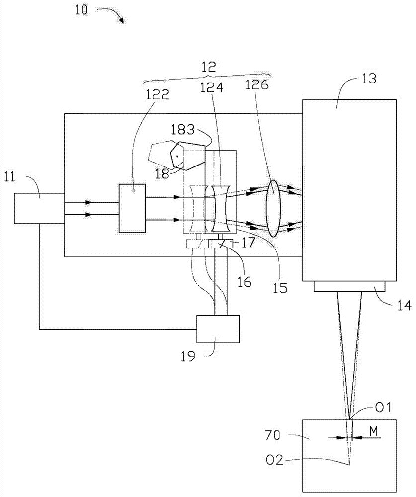
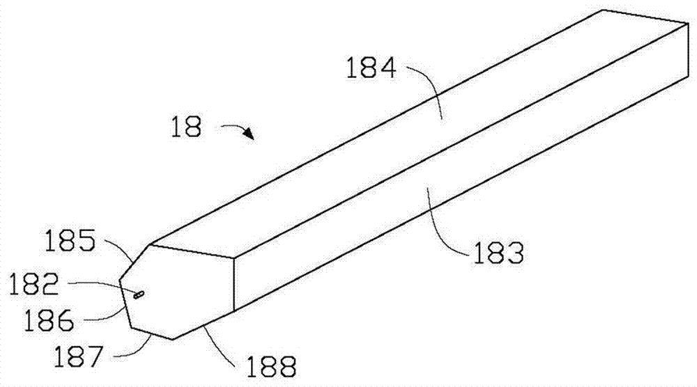
[0027] see figure 1 , is the laser output device 10 provided in the first embodiment of the present invention. The laser output device 10 includes a laser 11 , an optical element 12 , a laser scanning galvanometer 13 , a focusing lens 14 , a storage device 15 , a translation device 16 , a position sensing device 17 , a stopper device 18 , and a controller 19 .

[0028] The laser 11 is used to generate a laser beam. The optical element 12 includes a laser beam expander 122 , a concave lens 124 and a convex lens 126 . The laser beam expander 122 is used to expand the laser beam generated from the laser 11 . The concave lens 124 is used to diverge the laser beam from the laser beam expander 122 . The convex lens 126 is used to converge the laser beam from the concave lens 124 . The laser scanning galvanometer 13 is used to deflect the laser beam from the convex lens 126 at a certain angle and output it to a region to be printed. The focusing lens 14 is arranged at the front ...

no. 2 approach

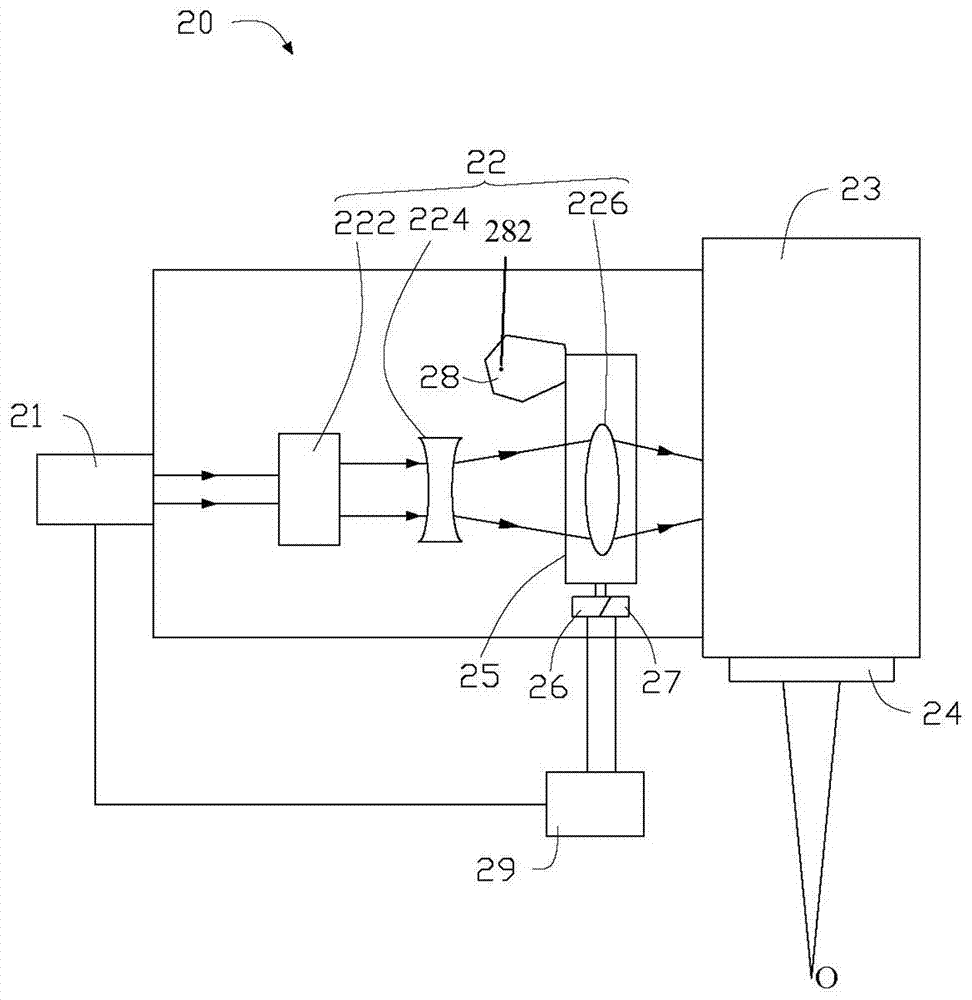
[0036] see image 3 , is the laser output device 20 provided in the second embodiment of the present invention. The laser output device 20 includes a laser 21 , an optical element 22 , a laser scanning galvanometer 23 , a focusing lens 24 , a storage device 25 , a translation device 26 , a position sensing device 27 , a stopper device 28 , and a controller 29 .

[0037] The laser 21 is used to generate a laser beam. The optical element 22 includes a laser beam expander 222 , a concave lens 224 and a convex lens 226 . The laser beam expander 222 is used to expand the laser beam generated from the laser 21 . The concave lens 224 is used to diverge the laser beam from the laser beam expander 222 . The convex lens 226 is used to converge the laser beam from the concave lens 224 . The laser scanning galvanometer 23 is used to deflect the laser beam from the convex lens 226 at a certain angle and output it to a region to be printed. The focusing lens 24 is arranged at the front...

no. 3 approach

[0045] see Figure 4 , is the laser output device 30 provided in the third embodiment of the present invention. The laser output device 30 includes a laser 31 , an optical element 32 , a laser scanning galvanometer 33 , a focusing lens 34 , a storage device 35 , a translation device 36 , a position sensing device 37 , a stopper device 38 , and a controller 39 .

[0046] The laser 31 is used to generate a laser beam. The optical element 32 includes a laser beam expander 322 , a concave lens 324 and a convex lens 326 . The laser beam expander 322 is used to expand the laser beam generated from the laser 31 . The concave lens 324 is used to diverge the laser beam from the laser beam expander 322 . The convex lens 326 is used to converge the laser beam from the concave lens 324 . The laser scanning galvanometer 33 is used to deflect the laser beam from the convex lens 326 at a certain angle and output it to an area to be printed. The focusing lens 34 is arranged on the front ...


PUM


Abstract

The invention relates to a laser output device, which includes a controller, lasers, optical elements, laser scanning vibrating mirrors and focusing lenses arranged in sequence. The laser is used to generate a laser beam, and the laser beam enters the laser scanning vibrating mirror through the optical element and is output to a region to be printed, and then converges to a scanning focus through the focusing lens. The laser output device also includes a translation device, a position sensing device and a stopper device electrically connected to the controller. The translation device is used to drive the optical element to move, and the position sensing device is used to detect the position of the driven optical element. The stopping device is arranged on the moving route of the optical element and can stop the optical element at different positions, thereby changing the position of the scanning focus. The invention also provides a 3D printer with the laser output device.

Description

technical field [0001] The invention relates to the technical field of 3D printing, in particular to a laser output device and a 3D printer with the laser output device. Background technique [0002] 3D printer, also known as three-dimensional printer, is a kind of rapid prototyping technology, based on digital model files, using metal or non-metallic materials to form powder, melting / melting the laid flat powder to be formed layer by layer, and then Solidification build-up molding to construct three-dimensional solid printing equipment. With the rapid development of 3D printing technology, 3D printers have been widely used in product manufacturing. Among them, the laser output device is an important part of the 3D printer. [0003] At present, the laser output device usually uses a simple fixed-focus optical path, and there are two situations for the laser scanning sintering point: first, the laser scanning sintering and melting / melting of the powder to be formed by the l...

Claims


Application Information

Patent Timeline
Patent Type & Authority Patents(China)
IPC IPC(8): B29C64/153B29C64/268B22F3/105B33Y30/00
CPCB33Y30/00B22F10/00B22F12/44B22F12/49B22F12/90B22F10/28B22F12/47Y02P10/25
Inventor 刘建业胡高峰梁崇智徐卡里牛留辉李栖凤朱昊威
Owner GUANGDONG HANBANG 3D TECH CO LTD
Why Eureka
Try Eureka