Initiative guiding method and initiative guiding device of railway vehicle wheel pair
An actively oriented, rail vehicle technology, applied in the field of steering technology of rail vehicle bogies, to achieve the effect of reducing the risk of derailment
- Summary
- Abstract
- Description
- Claims
- Application Information
AI Technical Summary
Problems solved by technology
Method used
Image

Examples
Embodiment Construction
[0035] The present invention will be further described below in conjunction with accompanying drawing.
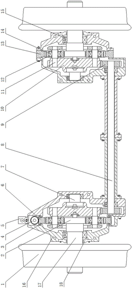
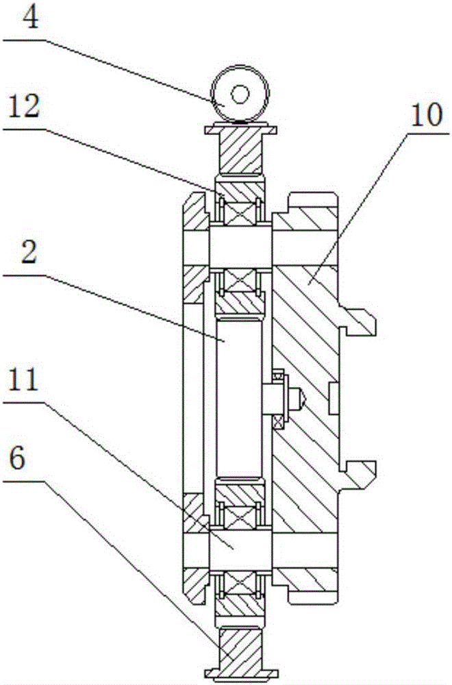
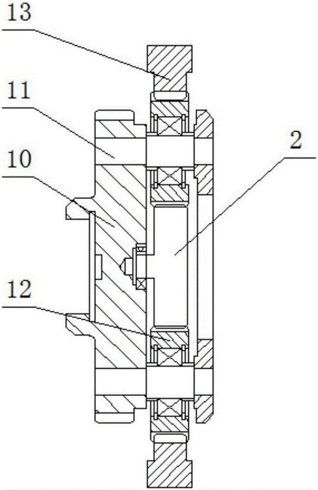
[0036] An active guiding device for a rail vehicle wheel set, comprising an independent wheel set 1 fixed at one end of a half shaft 17, the inner side of the independent wheel set 1 is respectively provided with two sets of left and right planetary gear trains, the sun gear 2 of the planetary gear train and the independent wheel set The half shaft 17 of pair 1 is fixed, the planetary gear 12 of the planetary gear train is fixed to the planetary carrier 10 through the bearing 14 arranged on the planetary wheel shaft 11, and the planetary carrier 10 is connected to the half shaft 17 through the sun gear 2 meshing with the planetary gear 12, The end face of the planetary carrier 10 is fixed to the casing 16 through the connecting shaft 7 and its bearing 15. The outer ring of the planetary carrier 10 is provided with an outer ring gear meshed with the transmission gear 9 fixed ...
PUM
 Abstract
Description
Claims
Application Information
 - R&D
- Intellectual Property
- Life Sciences
- Materials
- Tech Scout
- Unparalleled Data Quality
- Higher Quality Content
- 60% Fewer Hallucinations
Browse by: Latest US Patents, China's latest patents, Technical Efficacy Thesaurus, Application Domain, Technology Topic, Popular Technical Reports.
© 2025 PatSnap. All rights reserved.Legal|Privacy policy|Modern Slavery Act Transparency Statement|Sitemap|About US| Contact US: help@patsnap.com