Temperature and humidity control system of point switch

A temperature and humidity control, switch machine technology, applied in the control/regulation system, non-electric variable control, simultaneous control of multiple variables, etc. , decay and other problems, to achieve the effect of reducing the risk of train derailment, simple control algorithm and good robustness

Pending Publication Date: 2020-05-08
EAST CHINA JIAOTONG UNIVERSITY
View PDF0 Cites 0 Cited by
  • Summary
  • Abstract
  • Description
  • Claims
  • Application Information

AI Technical Summary

Problems solved by technology

Use the information fed back from the switch machine to judge whether the switch rail is closely attached to the basic rail. When the switch machine fails, it will appear that the console has received that the switch machine has completed the conversion of the switch position and the switch rail has failed. The situation of sticking to the basic track leads to misjudgment, which in turn leads to serious losses
[0003] At present, the electro-hydraulic switch machines commonly used on railways are affected by weather conditions, which will lead to failure of their internal mechanisms. For example, when the temperature is low, the oil in the oil cylinder and oil pipe will freeze, causing the hydraulic transmission system to fail. cause serious safety accidents
In addition, the switch machine is in a closed state, and the long-term internal environment with high humidity will cause the internal parts to rot, especially once the transmission mechanism rots, it will appear jamming, which will lead to a decrease in the life of the switch machine, and there is a certain degree of safety. Hidden danger
[0004] In the existing technology, the monitoring of the fault state of the switch machine is mainly to monitor the gap of the switch machine, and then judge whether the switch machine is working normally, but there is no effective solution for the environmental control inside the switch machine

Method used


Image

  • Temperature and humidity control system of point switch
  • Temperature and humidity control system of point switch
  • Temperature and humidity control system of point switch

Examples


Embodiment Construction

[0029] The present invention will be described in further detail below in conjunction with the embodiments and with reference to the accompanying drawings.

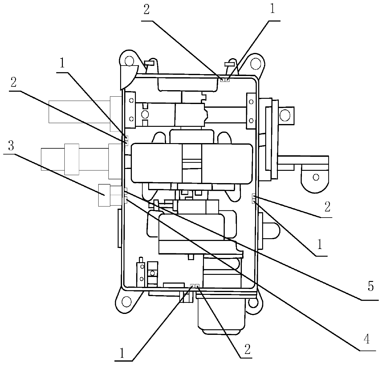
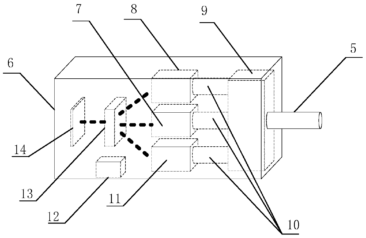
[0030] see Figure 1 to Figure 8Shown is a switch machine temperature and humidity control system and method in the present invention, including a temperature sensor 1, a humidity sensor 2, a temperature and humidity adjustment device 3, an air outlet pipe 4, and an air inlet pipe 5.

[0031] Such as figure 1 As shown, the temperature and humidity adjustment device 3 is installed outside the switch machine, close to the switch machine, and the temperature sensor 1 and the humidity sensor 2 are respectively installed on the four sides of the switch machine inner wall, and the temperature sensor 1 is used to detect The temperature information inside the switch machine, the humidity sensor 2 is used to detect the humidity information inside the switch machine, the temperature sensor 1 and the humidity sensor 2 send the coll...


PUM


Abstract

The invention discloses a temperature and humidity control system of a point switch. A temperature sensor and a humidity sensor are respectively arranged on four surfaces of the inner wall of the point switch. The temperature sensor and the humidity sensor send collected information to the temperature and humidity adjusting device for calculation and processing. The average value of the temperature values acquired by the temperature sensors on the four surfaces is used as the temperature value inside the point switch, and the average value of the humidity values acquired by the humidity sensors is used as the humidity value inside the point switch. A PID control algorithm is adopted to adjust the working states of the temperature and humidity adjusting device and the air inlet pipe so as to adjust the temperature and humidity in the point switch, so that the point switch works in an ideal environment, the service life of the point switch is prolonged, and the risk of train derailment caused by faults of the point switch is reduced.

Description

technical field [0001] The invention relates to the field of temperature and humidity control of a switch machine, in particular to a temperature and humidity control system of a switch machine. Background technique [0002] The switch machine refers to the important signal infrastructure equipment used to reliably change the position of the turnout, change the opening direction of the turnout, lock the tip rail of the turnout, and reflect the position of the turnout. It can well ensure driving safety, improve transportation efficiency, and improve the safety of driving personnel labor intensity. Use the information fed back from the switch machine to judge whether the switch rail is closely attached to the basic rail. When the switch machine fails, it will appear that the console has received that the switch machine has completed the conversion of the switch position and the switch rail has failed. The situation of sticking to the basic track leads to misjudgment, which in...

Claims


Application Information

Patent Timeline
Patent Type & Authority Applications(China)
IPC IPC(8): G05D27/02
CPCG05D27/02
Inventor 胡军
Owner EAST CHINA JIAOTONG UNIVERSITY
Why Eureka
Try Eureka