
Multi-inner-cavity structure design method for hollow fan blade

A fan blade and structural design technology, applied in calculation, special data processing applications, instruments, etc., can solve the problems of complex and cumbersome calculations, large calculation errors of stiffener trusses, and difficulty in smooth transition of stiffener trusses

Inactive Publication Date: 2016-07-27
NORTHWESTERN POLYTECHNICAL UNIV
View PDF4 Cites 17 Cited by
  • Summary
  • Abstract
  • Description
  • Claims
  • Application Information

AI Technical Summary

Problems solved by technology

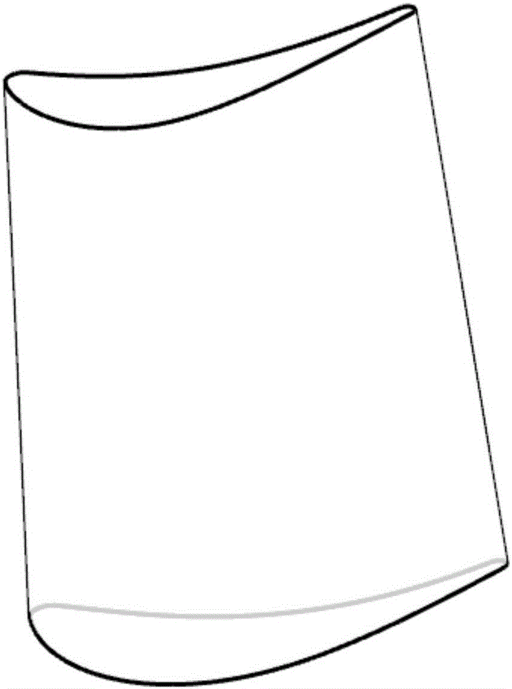
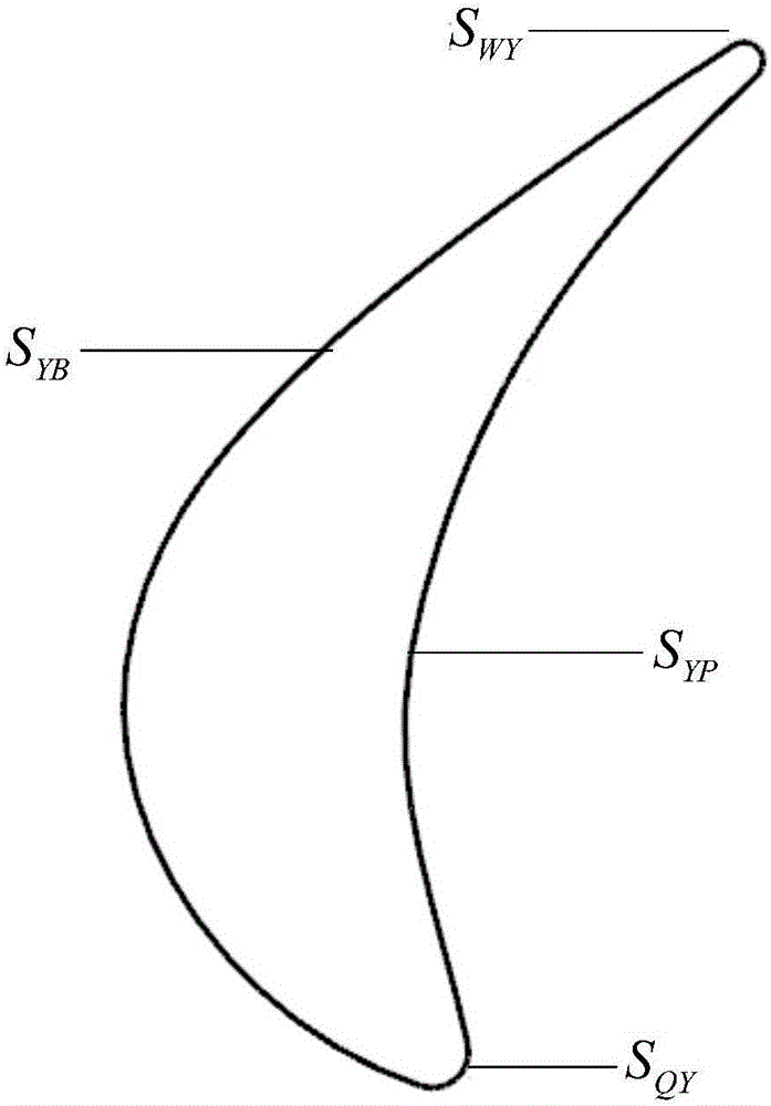
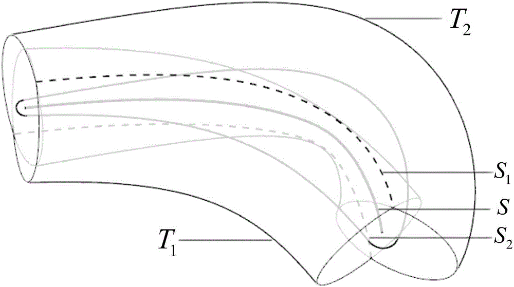
[0004] The purpose of the present invention is to propose a multi-cavity hollow fan blade for the design of the truss-type hollow fan blade in the prior art for the problems of relatively large calculation errors in the position and shape of the rib truss, complicated calculations, and difficulty in smooth transition of the rib truss. Structural Design Method

Method used


Image

  • Multi-inner-cavity structure design method for hollow fan blade
  • Multi-inner-cavity structure design method for hollow fan blade
  • Multi-inner-cavity structure design method for hollow fan blade

Examples


Embodiment Construction

[0047] Embodiments of the present invention are described in detail below, examples of which are shown in the drawings, wherein the same or similar reference numerals designate the same or similar elements or elements having the same or similar functions throughout. The embodiments described below by referring to the figures are exemplary and are intended to explain the present invention and should not be construed as limiting the present invention.

[0048] In describing the present invention, it should be understood that the terms "center", "longitudinal", "transverse", "length", "width", "thickness", "upper", "lower", "front", " Orientation indicated by rear, left, right, vertical, horizontal, top, bottom, inside, outside, clockwise, counterclockwise, etc. The positional relationship is based on the orientation or positional relationship shown in the drawings, which is only for the convenience of describing the present invention and simplifying the description, rather than ...


PUM


Abstract

The invention provides a multi-inner-cavity structure design method for a hollow fan blade. The method comprises the following steps: constructing a blade body contour 3D model; performing region partition on a blade body; building cavity entities in corresponding regions; and lastly, performing subtract of the Boolean operation to obtain a final hollow fan blade. The method has the beneficial effects that a complete multi-cavity hollow fan blade structure design method is provided, and a plurality of control points are provided in each of cavity regions in order to ensure implementation of smooth transition and setting of unequal wall thicknesses. Through use of the method, a multi-cavity region accurate layout can be obtained and a multi-cavity blade can be generated automatically in a way of only inputting wall thickness parameters and position parameters. The method has no limitation on a platform of three-dimensional software, and multi-cavity hollow fan blade design can be performed on a plurality of software platforms through the method.

Description

technical field [0001] The invention relates to the technical field of hollow fan blade design, in particular to a method for designing a multi-cavity structure of a hollow fan blade. Background technique [0002] The fan blades of modern civilian large-duct ratio turbofan engines are mostly designed with wide-chord blades. Compared with narrow chord blades with bosses, wide chord blades have the advantages of increasing engine surge margin, resisting foreign object damage, increasing engine thrust, and reducing the number of blades, etc., and have been applied in engines. However, the centrifugal load of wide-chord fan blades increases, while meeting the reliability requirements, the mass of the wheel disc increases significantly. If the mass reduction design technology is not adopted, wide-chord fan blades will be difficult to apply to engines with large bypass ratios. For this reason, aero-engine companies such as RR and PW have vigorously developed the design technology...

Claims


Application Information

Patent Timeline
Patent Type & Authority Applications(China)
IPC IPC(8): G06F17/50
CPCG06F30/17
Inventor 莫蓉李辉杨彬
Owner NORTHWESTERN POLYTECHNICAL UNIV
Learn More