Piezoelectric material based fluid vibration energy collection apparatus

A technology of vibration energy collection and piezoelectric materials, applied in the direction of piezoelectric effect/electrostrictive or magnetostrictive motors, generators/motors, electrical components, etc. The electric transducer sheet has poor output power effect and single vibration frequency, etc., to achieve the effect of saving space, reducing physical size, and saving resources

Inactive Publication Date: 2016-07-27
JIANGSU UNIV
View PDF5 Cites 6 Cited by
  • Summary
  • Abstract
  • Description
  • Claims
  • Application Information

AI Technical Summary

Problems solved by technology

In 2011, Ma Huaan of Shanghai Jiaotong University and others designed a piezoelectric vibration energy emission and acquisition device based on environmental energy acquisition, which can broaden the 5Hz working frequency band, but still adopts the form of a cantilever beam. When the direction of environmental vibration is different from the vibration direction of the cantilever arm, Dramatically reduced deformation and limited range of use
[0009] The working principle of the piezoelectric device is to use the piezoelectric material to generate an electric field when it is deformed by external mechanical action to form an internal stress; in the prior art, there is a problem of single vibration frequency in the field of vibration energy collection of piezoelectric transducers , which leads to poor output power effect of the piezoelectric transducer when the vibration frequency in the environment is not easy to reach the natural frequency

Method used


Image

  • Piezoelectric material based fluid vibration energy collection apparatus
  • Piezoelectric material based fluid vibration energy collection apparatus
  • Piezoelectric material based fluid vibration energy collection apparatus

Examples


Embodiment Construction

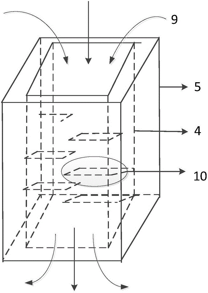
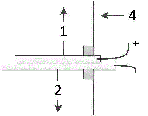
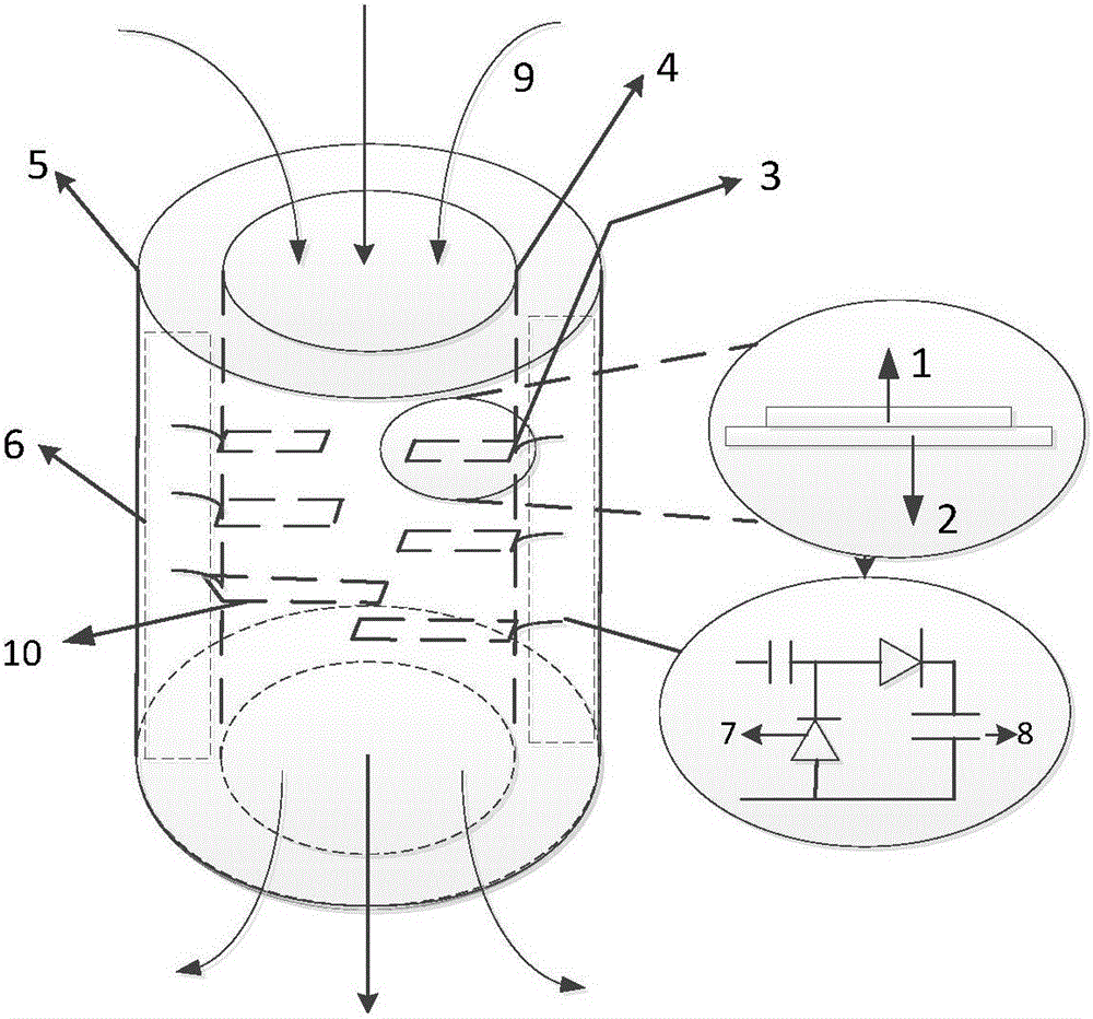
[0036] In conjunction with the accompanying drawings, a fluid vibration energy collection device based on piezoelectric materials includes a first container 5 and a second container 4; the first container 5 and the second container 4 are cuboids or cylinders; the first container 5. The second container 4 is of the same height and is a hollow structure, and the second container 4 is set in the first container 5; between the first container 5 and the second container 4, there are several transducer circuits 6 placed on the PCB board , the upper and lower end surfaces between the first container 5 and the second container 4 are sealed; the inside of the second container 4 has several sockets 3, one end of the piezoelectric transducer sheet 10 is fixed in the socket 3, and the other end of the piezoelectric transducer sheet 10 is One end extends horizontally to the inner side of the second container 4; the piezoelectric transducer sheet 10 includes a piezoelectric ceramic 1 and a s...


PUM


Abstract

The invention discloses a piezoelectric material based fluid vibration energy collection apparatus. The fluid vibration energy collection apparatus comprises a first container and a second container, wherein the first container and the second container are cuboids or cylinders; the second container is sleeved by the first container; multiple transduction circuits arranged on a PCB are arranged between the first container and the second container; the upper and lower end planes between the first container and a second container are sealed; multiple sockets are formed in the inner side of the second container; one ends of piezoelectric transduction sheets are fixed in the sockets while the other ends of the piezoelectric transduction sheets extend to the center of the second container; the piezoelectric transduction sheets comprise piezoelectric ceramics and substrates; the piezoelectric ceramics are connected with the positive ends of the corresponding transduction circuits through wire-outlet circuits; the substrates are connected with the negative ends of the corresponding transduction circuits through the wire-outlet circuits; the number of the transduction circuits is equal to that of the piezoelectric transduction sheets, and the transduction circuits are in one-to-one correspondence connection with the piezoelectric transduction sheets. According to the apparatus, the broadband is realized and the energy collection effect is improved due to different lengths, shape structures and position relations of the piezoelectric transduction sheets.

Description

technical field [0001] The invention belongs to the field of vibration energy collection, in particular to a fluid vibration energy collection device based on piezoelectric materials. Background technique [0002] The phenomenon that piezoelectric materials can generate charge under the action of external force has been discovered for decades, but limited by the power generation capacity of piezoelectric materials, this part of the charge is collected and stored as a power source for driving micro-power appliances. Always very little. In recent years, the use of highly integrated low-power electronic components and radio frequency technology has provided the premise for the application of piezoelectric energy harvesting technology. In addition, the power consumption of sensors, microprocessors and radio frequency devices has been continuously reduced, and the energy balance of the system has gradually become balanced. Micro-environmental energy harvesting technology has onc...

Claims


Application Information

Patent Timeline
Patent Type & Authority Applications(China)
IPC IPC(8): H02N2/18
CPCH02N2/185
Inventor 白雪潘祎雯赵文祥徐雷钧
Owner JIANGSU UNIV
Why Eureka
Try Eureka