Grooving device for mold

A mold and groove box technology, which is applied in the field of mold grooving devices, can solve the problems of reducing the number of grooving, slowing down the efficiency of grooving, and high difficulty in operation, so as to reduce the difficulty and amount of operation, increase the number of successful grooving and digging Slot accuracy, the effect of increasing the number of slots

Inactive Publication Date: 2016-08-03
CHANGZHOU JINCHENGYU HARDWARE
View PDF7 Cites 4 Cited by
  • Summary
  • Abstract
  • Description
  • Claims
  • Application Information

AI Technical Summary

Problems solved by technology

In the process of mold processing, there are often grooves on the mold body. At present, most of them use sleeves for digging operations. Sleeve digging will make the excavated part of the body stuck inside the sleeve. It is often necessary to remove the residue when digging on one side, but at present, most of the residue is cleaned manually. The cleaner first smashes the residue with an iron rod, and then turns the sleeve over, so that the residue falls out of the sleeve, but The amount of manual cleaning operations is large, the operation is difficult, time-consuming and labor-intensive, which slows down the efficiency of trenching and reduces the number of trenches

Method used


Image

  • Grooving device for mold
  • Grooving device for mold
  • Grooving device for mold

Examples


Embodiment Construction

[0018] The following will clearly and completely describe the technical solutions in the embodiments of the present invention with reference to the accompanying drawings in the embodiments of the present invention. Obviously, the described embodiments are only some, not all, embodiments of the present invention. Based on the embodiments of the present invention, all other embodiments obtained by persons of ordinary skill in the art without making creative efforts belong to the protection scope of the present invention.

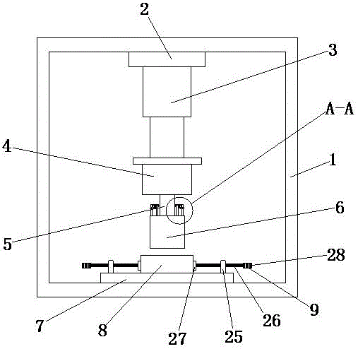
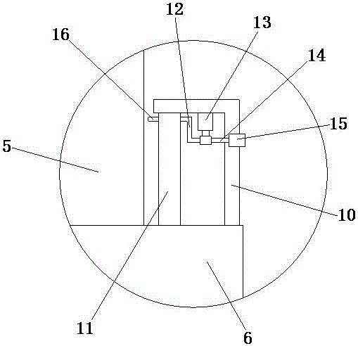
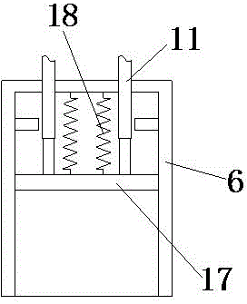
[0019] see Figure 1-4 , the present invention provides a technical solution: a mold grooving device, including a housing 1, the top of the inner wall of the housing 1 is provided with a base 2, the bottom of the base 2 is fixedly connected with the electric push rod 3, and the electric push rod 3 The free end of the rotating motor 4 is fixedly connected to the rotating motor 4 through the connecting plate, the rotating shaft 5 is arranged on the side away fro...


PUM


Abstract

The invention discloses a grooving device for a mold. The grooving device comprises a shell body. A pedestal is arranged at the top of the inner wall of the shell body. The bottom of the pedestal is fixedly connected with an electric pushing rod. The free end of the electric pushing rod is fixedly connected with a rotating motor through a connecting plate. A rotating shaft is arranged on the side, away from the connecting plate, of the rotating motor. The side, away from the rotating motor, of the rotating shaft is fixedly connected with a grooving box. A base is fixedly connected to the bottom of the inner wall of the shell body. A mold embryo body used cooperatively with the grooving box is fixedly installed at the top of the base, and clamping devices are symmetrically arranged on the two sides of the mold embryo body. According to the grooving device for the mold, a telescopic rod pushes a pushing plate to move downwards through the thrust produced by gas, accordingly, residues on the inner wall of the grooving box are removed, manual cleaning is not needed, the operation difficulty and the operation quantity of workers are reduced, the time and effort are saved, the grooving efficiency is improved, the grooving amount is increased, the applicability is high, and using of the grooving device by people is convenient.

Description

technical field [0001] The invention relates to the technical field of mold processing, in particular to a mold groove digging device. Background technique [0002] Mold processing refers to the processing of forming and billet tools, and also includes shearing dies and die-cutting dies. Usually, the mold consists of two parts, the upper mold and the lower mold. The steel plate is placed between the upper and lower molds, and the material is formed under the action of the press. When the press is opened, the workpiece determined by the shape of the mold is obtained or the corresponding waste is removed. Workpieces as small as electronic connectors and as large as automotive dashboards can be molded. In the process of mold processing, there are often grooves on the mold body. At present, most of them use sleeves for digging operations. Sleeve digging will make the excavated part of the body stuck inside the sleeve. It is often necessary to remove the residue when digging o...

Claims


Application Information

Patent Timeline
Patent Type & Authority Applications(China)
IPC IPC(8): B21D37/20B29C33/38
CPCB21D37/20B29C33/3842
Inventor 陆中明
Owner CHANGZHOU JINCHENGYU HARDWARE
Why Eureka
Try Eureka