
Deployable joint locking control mechanism

A technology of locking control and joints, which is applied in the direction of manipulators, manufacturing tools, joints, etc., and can solve problems such as high energy consumption, bulky mechanism, and limited locking force

Inactive Publication Date: 2016-08-03
SOUTHWEST UNIV
View PDF7 Cites 6 Cited by
  • Summary
  • Abstract
  • Description
  • Claims
  • Application Information

AI Technical Summary

Problems solved by technology

The above two types of mechanisms are currently the mainstream design principles of joint locking control mechanisms including robots. The main disadvantages of friction locking mechanisms are limited locking force, relatively bulky mechanisms and high energy consumption; the main disadvantages of dual-state locking mechanisms It can only provide discrete rather than continuous angular (or linear) locking positions, and the improvement of resolution must be at the expense of increasing the size of the mechanism or reducing the ultimate locking force

Method used


Image

  • Deployable joint locking control mechanism
  • Deployable joint locking control mechanism
  • Deployable joint locking control mechanism

Examples


Embodiment Construction

[0026] Mechanisms involved in the field of robotics are often track-determined or controlled, in other words, the degree of freedom of the mechanism is equal to the number of effective power sources (such as motors). Therefore, the locking or releasing of a single-degree-of-freedom motion joint should at least be carried out under the condition that the trajectory of the mechanism is determined or controlled, that is, at this time, the movement of each joint of the mechanism does not deviate from the predetermined trajectory due to a small external force (moment). Including the joint being locked or released. On the other hand, the locking or releasing of the joints means that the degree of freedom of the robot mechanism changes accordingly. People use this process to control the topological change or special movement of the robot to achieve energy saving and simplification. Similar applications are in reference It can be seen in literature [1], [2], [3]. In order to explain ...


PUM


Abstract

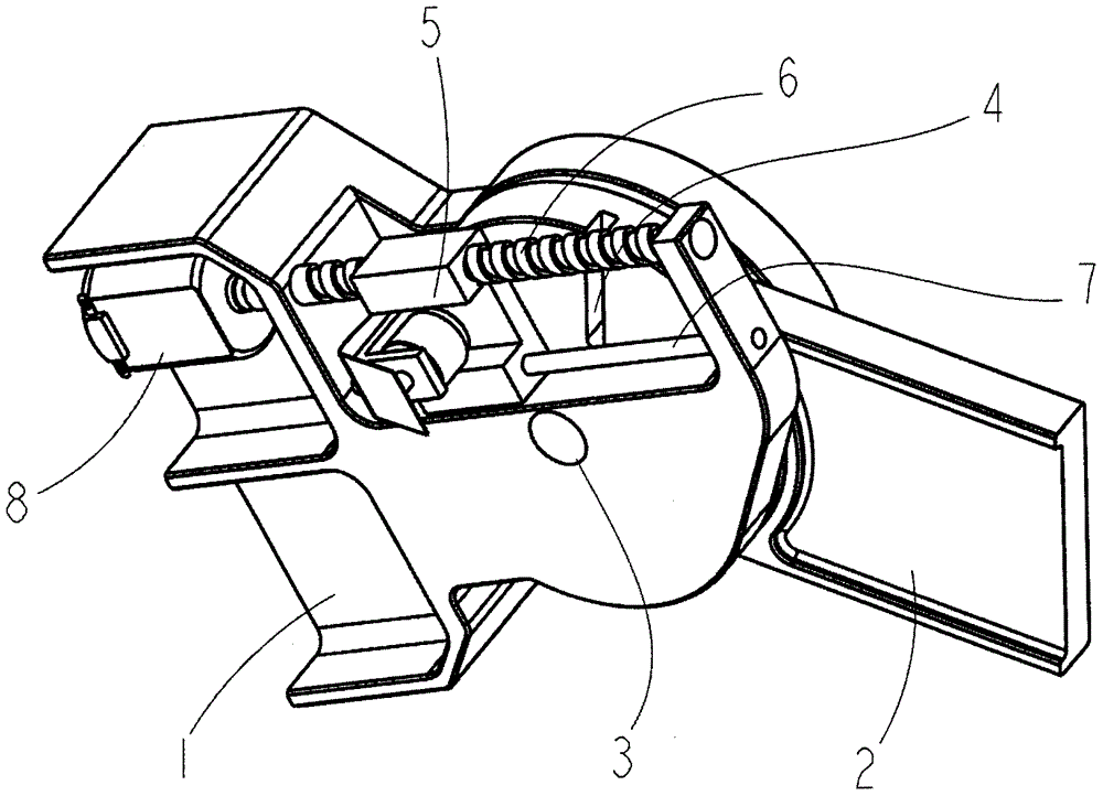
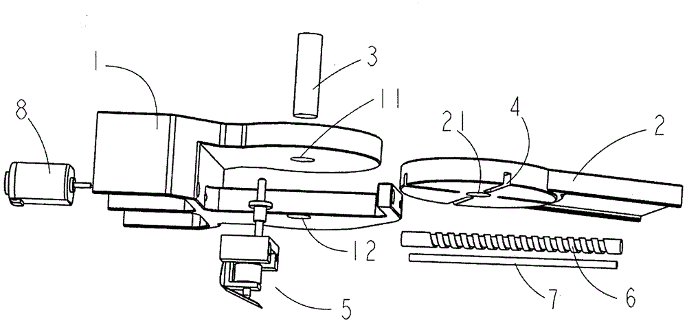
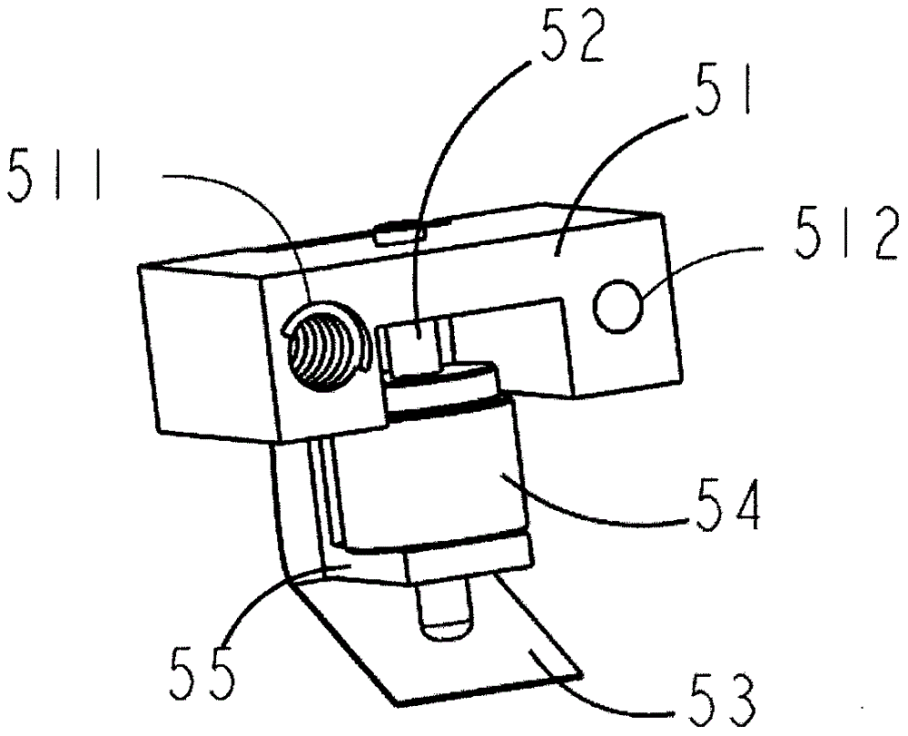
The invention discloses a deployable joint locking control mechanism which can be used for a common single-freedom-degree rotary joint. The deployable joint locking control mechanism is composed of a joint, a joint upper arm (1), a joint forearm (2), a joint rotating shaft (3), a joint locking groove (4), a joint locking control block (5), a lead screw (6), a guide rail (7) and a lead screw driver (8). The deployable joint locking control mechanism is used for locking rotation of the joint forearm around the joint rotating shaft relative to the joint upper arm through insertion fit between a joint locking pin and a locking groove located in the forearm; transmission of the lead screw and the guide rail is used, a special shape of the locking groove is used in a matched manner, and the function of locking at any joint corner position is achieved. According to the deployable joint locking control mechanism, the locking force which is much larger than that capable of being provided by a friction type clutch device is provided under the same design size scale; meanwhile, continuous rather than discrete joint corner locking position can be provided; and meanwhile, the deployable joint locking control mechanism is quiet energy-saving, small, exquisite and compact.

Description

technical field [0001] The invention relates to a kinematic joint locking control mechanism, especially for the locking and release control of the rotary kinematic joints of a robot, and can also be used for the clutch control of the kinematic kinematic joints of other kinematic mechanisms. technical background [0002] At present, robot technology still has many bottlenecks and limitations in the face of complex and diverse earth environments and human production and life tasks, among which there are many problems about the applicability of motion mechanisms. This encourages people to make bold improvements and innovations in robot motion modes and mechanisms, making them more flexible and able to adapt to more tasks and environments, and these new modes and mechanisms can also be used in other fields besides robots. [0003] Reconfigurable robotic mechanism is one of the new technologies developed in the 1990s. Early research on reconfigurable robotic mechanism was keen on...

Claims


Application Information

Patent Timeline
Patent Type & Authority Applications(China)
IPC IPC(8): B25J17/02
CPCB25J17/0258
Inventor 张春
Owner SOUTHWEST UNIV
Learn More