Plastic cylinder three-point positioning and punching mechanism

A three-point positioning, cylinder technology, applied in metal processing and other directions, can solve the problems of no specific clamping device, affecting the punching effect, and deformation of the cylinder, so as to achieve firm clamping and fixing, good effect, and disassembly and replacement. handy effect

Active Publication Date: 2016-08-03
平邑仁安中医药产业发展有限公司
View PDF5 Cites 13 Cited by
  • Summary
  • Abstract
  • Description
  • Claims
  • Application Information

AI Technical Summary

Problems solved by technology

[0002] When the existing cylindrical plastic products need to be punched on the side wall, it needs to use equipment to clamp the cylinder body, but there is no specific clamping device at present, and it generally uses two screw rods to be screwed on the support plate On the other hand, throu

Method used


Image

  • Plastic cylinder three-point positioning and punching mechanism
  • Plastic cylinder three-point positioning and punching mechanism
  • Plastic cylinder three-point positioning and punching mechanism

Examples


Example Embodiment

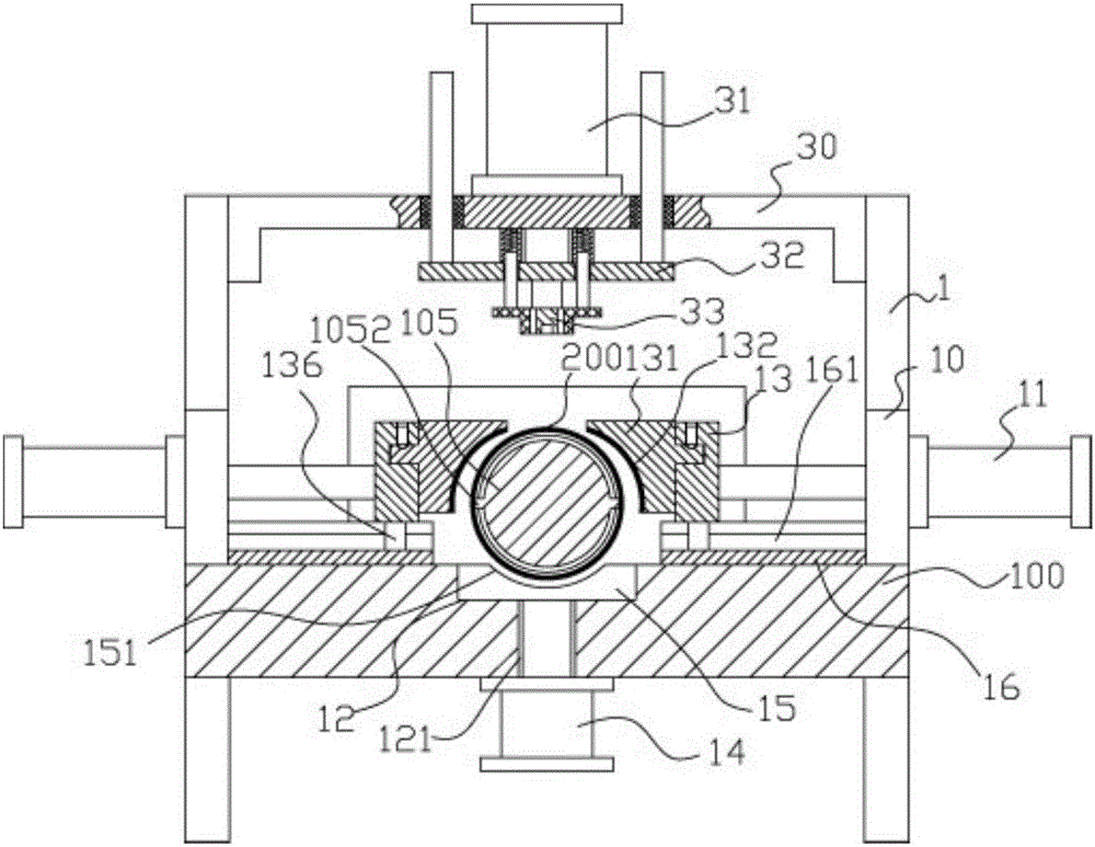
[0023] Example: see Figure 1 to Figure 5 As shown, a three-point positioning and punching mechanism for a plastic cylindrical body includes a frame 100. The top surface of the top plate of the frame 100 is fixed with an upper support plate 10, and the middle of the top surface of the two upper support plates 10 It has an upper extension 1, the two ends of the middle connecting frame 30 are fixedly connected to the two upper extensions 1 by bolts, the middle top surface of the middle connecting frame 30 is fixed with a punching cylinder 31, and the push rod of the punching cylinder 31 is vertical Passing down the middle of the middle connecting frame 30, a guide plate 32 is fixed at the middle of the push rod of the punching cylinder 31, and the end of the push rod of the punching cylinder 31 extends out of the guide plate 32 and is fixed with a punch 33;

[0024] The front part of the top plate of the frame 100 is fixed with a connecting support plate 101, a guide connecting sle...


PUM


Abstract

The invention discloses a plastic cylinder three-point positioning and punching mechanism which comprises a frame. Upper supporting plates are fixed to the top faces of the two sides of a top plate of the frame, and upper extending parts are arranged on the middle portions of the top faces of the two upper supporting plates. The two ends of a middle connecting rack are fixedly connected to the two upper extending parts through bolts, and a punching air cylinder is fixed to the top face of the middle of the middle connecting rack. A push rod of the punching air cylinder vertically and downwards penetrates through the middle of the middle connecting rack, a guiding plate is fixed to the middle of the push rod of the punching air cylinder, and a punch is fixed to the end, extending out of the guiding plate, of the push rod of the punching air cylinder. A connecting groove is formed in the middle of the top face of the top plate of the frame. A cylinder is clamped automatically in a three-point positioning mode through two arc grooves and an upper arc groove by means of clamping air cylinders and a lifting air cylinder, and a middle-supporting column is inserted into the cylinder to achieve middle-supporting; automatic punching is achieved, the cylinder cannot deform in punching, the cylinder is fixedly and firmly clamped, and the effect is good.

Description

Technical field: [0001] The invention relates to the technical field of plastic processing equipment, in particular to a three-point positioning punching mechanism for a plastic cylinder. Background technique: [0002] When the existing cylindrical plastic products need to be punched on the side wall, it needs to use equipment to clamp the cylinder body, but there is no specific clamping device at present, and it generally uses two screw rods to be screwed on the support plate On the other hand, through the rotation of the two screws, the clamp blocks fixed at the ends of the two screws clamp and fix the cylinder, and then the manual cutting is very troublesome, and when punching, because the inside of the cylinder is Hollow, it is easy to deform the cylinder and affect the punching effect. Invention content: [0003] The purpose of the present invention is to address the deficiencies of the prior art, and to provide a three-point positioning punching mechanism for a plas...

Claims


Application Information

Patent Timeline
IPC IPC(8): B26F1/02B26D7/02B26D7/01B26D7/00
CPCB26D7/00B26D7/01B26D7/02B26D2007/0012B26D2007/013B26F1/0053B26F1/02
Inventor 付淑珍
Owner 平邑仁安中医药产业发展有限公司
Why Eureka
Try Eureka