Powder recycling post-processing system

A powder and sealed cavity technology, applied in the field of powder recovery post-processing system, can solve the problems of powder not easily scattered and polluted

Inactive Publication Date: 2016-08-03
MICROJET TECH
View PDF2 Cites 8 Cited by
  • Summary
  • Abstract
  • Description
  • Claims
  • Application Information

AI Technical Summary

Problems solved by technology

[0006] The purpose of the present invention is to provide a powder recovery post-processing system to solve the shortcomings of the known three-dimensional molding mechanism design, such as powder spreading, printing and taking out the molded product, the dust raised will cause pollution to the working environment, etc. The environment is not polluted by the air of the powder, and the object put into the sealed chamber of the system can be processed after powder recovery, and a filter screen is

Method used


Image

  • Powder recycling post-processing system
  • Powder recycling post-processing system
  • Powder recycling post-processing system

Examples


Embodiment Construction

[0034] Some typical embodiments embodying the features and advantages of the present invention will be described in detail in the description in the following paragraphs. It should be understood that the present invention is capable of various changes in different aspects without departing from the scope of the present invention, and that the description and illustrations therein are illustrative in nature and not restrictive. this invention.

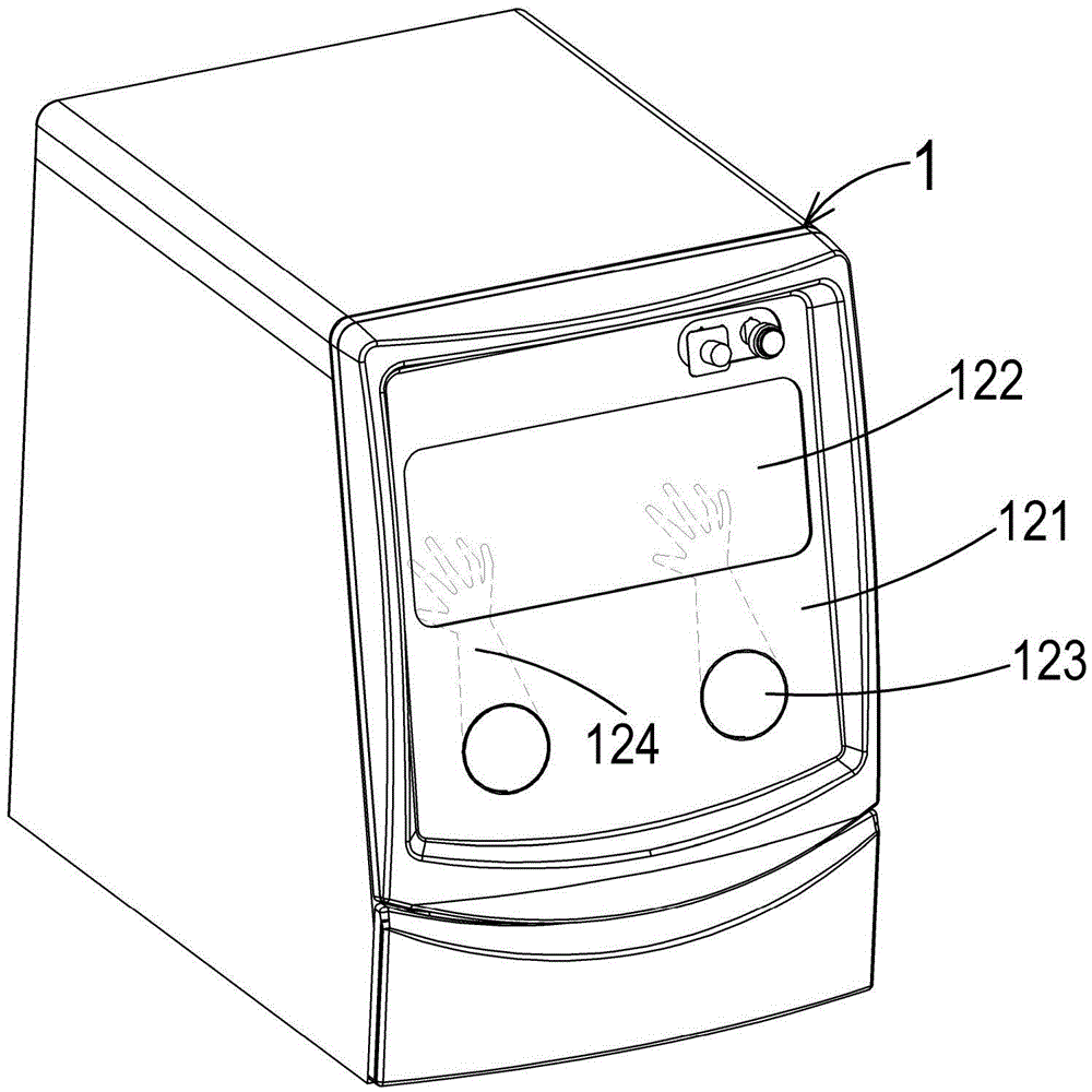
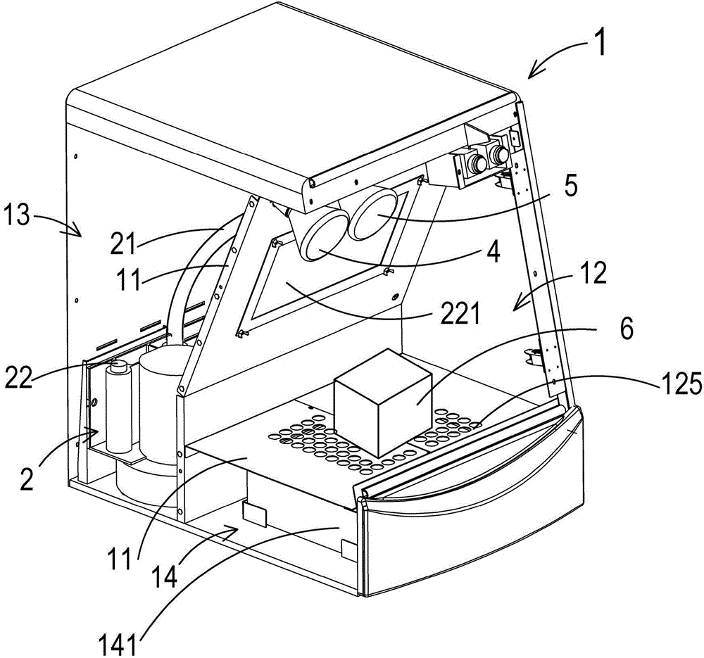
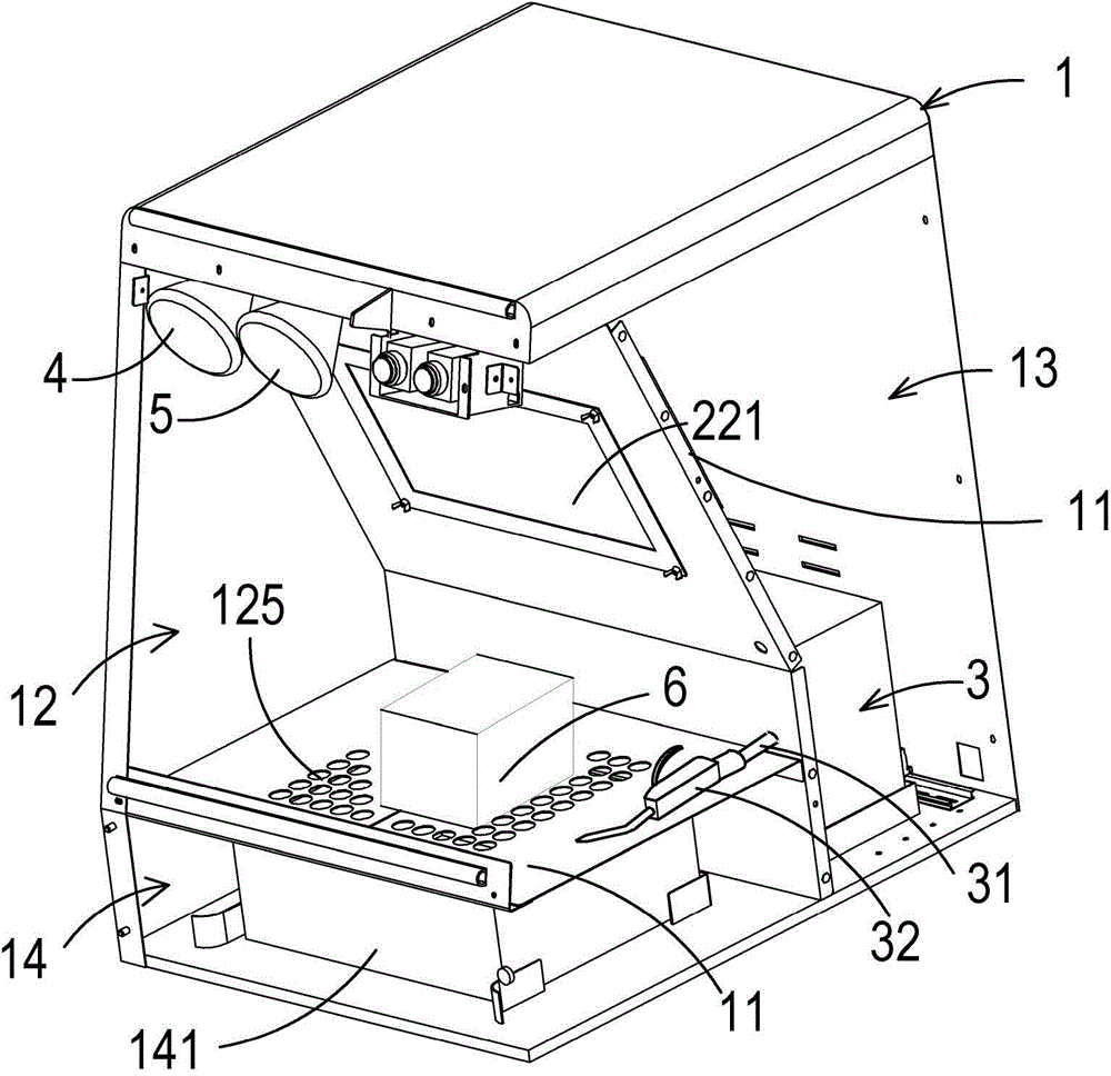
[0035] As shown in Figures 1 to 4, the powder recycling post-processing system of the present invention mainly includes a sealing body 1, a negative pressure device 2, an air pressure generating device 3, a lighting lamp 4 and a heating lamp 5.

[0036] The sealed body 1 has a sealed chamber 12 separated by a plurality of partitions 11, a device placement space 13 and a rest material placement space 14 are isolated from each other, and the sealed chamber 12 can accommodate the 3D molded object 6 for further processing Material powder r...


PUM


Abstract

The invention discloses a powder recycling post-processing system which is a 3DRP post-processing device with powder removal and recycling functions. The powder recycling post-processing system is used for automatically removing excessive powder after object forming, and is used for recycling powder with impurities being filtered and screened. The powder recycling post-processing system comprises a sealing main body, an air spraying column device, a negative-pressure device, an air pressure generating device, an illuminating lamp and a heating lamp.

Description

【Technical field】 [0001] The invention relates to a 3DRP rapid prototyping post-processing device, in particular to a powder recycling post-processing system. 【Background technique】 [0002] Rapid prototyping technology (RP technology for short) is a technology derived from the concept of building pyramid layer stacking, which can quickly and low-cost shape the designer's idea in a short time and present it to the public. The main feature is the quickness of forming. It can automatically and quickly convert the design scheme of any complex shape into a 3D solid model without any tools, molds and jigs, which greatly shortens the development cycle of new products and Reduce the cost of research and development, and can ensure the time to market of new products and the success rate of new product development at one time. It promotes a more complete and It is a convenient product design communication tool, thereby significantly improving the competitiveness of products in the m...

Claims


Application Information

Patent Timeline
IPC IPC(8): B29C67/00B08B15/04B33Y40/00
Inventor 陈智凯黄启峰
Owner MICROJET TECH
Why Eureka
Try Eureka