Sparse optical synthetic aperture imaging method based on subaperture shutter modulation phase difference method

A synthetic aperture, sparse optics technology, applied in the re-radiation of electromagnetic waves, the use of re-radiation, measurement devices, etc., can solve the problems of image loss, affecting the accuracy of common-phase detection, restoring image quality, increasing system complexity and cost, etc.

Inactive Publication Date: 2016-08-03
INST OF OPTICS & ELECTRONICS - CHINESE ACAD OF SCI
View PDF3 Cites 24 Cited by
  • Summary
  • Abstract
  • Description
  • Claims
  • Application Information

AI Technical Summary

Problems solved by technology

At present, the optical synthetic aperture imaging technology using the phase difference method still has many limitations: the phase difference method is essentially an image-based inversion technology, which needs to detect the common phase error based on the collected image information, which is artificially used as prior information. The introduced aberration will inevitably cause the image to lose part of the information, thereby affecting the accuracy of co-phase detection and the quality of

Method used


Image

  • Sparse optical synthetic aperture imaging method based on subaperture shutter modulation phase difference method
  • Sparse optical synthetic aperture imaging method based on subaperture shutter modulation phase difference method
  • Sparse optical synthetic aperture imaging method based on subaperture shutter modulation phase difference method

Examples


Embodiment Construction

[0037] The present invention will be further described below in conjunction with the drawings and specific embodiments.

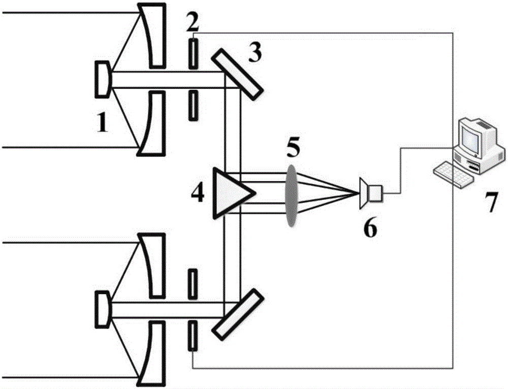
[0038] Taking the 2-aperture telescope array system as an example, the structure of the sparse optical synthetic aperture imaging system based on sub-aperture shutter modulation is as follows figure 1 As shown, it consists of two telescopes. In the figure, 1 is a telescope, 2 is an electronic shutter, 3 is a mirror, 4 is a beam combiner, 5 is an imaging lens, 6 is an imaging detection system, and 7 is a control processing computer. Control the processing computer. On the one hand, it controls the electronic shutter to switch on and off the imaging beams sequentially, and realizes the spatial modulation of the composite imaging system. On the other hand, it controls the imaging detection system to collect the corresponding modulated images and process the modulated images in real time. , To obtain sub-aperture aberration, common phase error between sub-apertur...


PUM


Abstract

The invention relates to a sparse optical synthetic aperture imaging method based on a subaperture shutter modulation phase difference method, and can be used for detecting aberration of all subapertures of a sparse optical synthetic aperture imaging system, co-phase error of multiple apertures and imaging beam atmospheric turbulence distortion and restoring the high-resolution image of a target in real time. Switching module is performed on each or multiple subapertures of the sparse optical synthetic aperture imaging system in turn by utilizing an electronic shutter, and the corresponding images are recorded by utilizing an image sensor. A series of recorded sub-images are processed by using the phase difference algorithm based on subaperture shutter modulation so that the subaperture aberration, the co-phase error of multiple apertures and the imaging beam atmospheric turbulence distortion can be detected simultaneously, and the high-resolution image of the target can be reconstructed. The sub-images having phase difference are generated by adopting shutter spatial modulation, and aberration detection and image restoration are integrated so that the method has advantages of being high in aberration detection precision, compact in structure, low in cost and convenient to use.

Description

Technical field [0001] The invention relates to a new sparse optical synthetic aperture imaging method, in particular to a sparse optical synthetic aperture imaging method based on a sub-aperture shutter modulation phase difference method, which can detect sub-aperture aberrations and multiple apertures in a sparse optical synthetic aperture imaging system The common phase error and the atmospheric turbulence distortion of the imaging beam, and the high-resolution image of the target can be restored in real time. Background technique [0002] With the continuous development of science and technology, space remote sensing technology has been widely used in many fields such as high-resolution imaging of the ground, military reconnaissance, astronomical observation, and deep space exploration. Spatial resolution is an important technical indicator for evaluating the observation capabilities of spaceborne remote sensors. The higher the resolution, the stronger the remote sensor’s abi...

Claims


Application Information

Patent Timeline
IPC IPC(8): G01S17/89
CPCG01S17/90
Inventor 马浩统亓波任戈谢宗良王智鹏史建亮崔占刚姜洋张美丽周建伟
Owner INST OF OPTICS & ELECTRONICS - CHINESE ACAD OF SCI
Why Eureka
Try Eureka