Link sensor

A sensor and connecting pin technology, applied in traction connectors, instruments, scientific instruments, etc., can solve problems such as inability to determine clearly

Inactive Publication Date: 2019-11-05
JOST WERKE GMBH
View PDF6 Cites 0 Cited by
  • Summary
  • Abstract
  • Description
  • Claims
  • Application Information

AI Technical Summary

Problems solved by technology

[0009] Similar disadvantages occur in all types of coupling arrangements of this type, in which case the driver of the vehicle cannot definitively determine whether a coupling connection that transmits tension is created

Method used


Image

  • Link sensor
  • Link sensor
  • Link sensor

Examples


Embodiment Construction

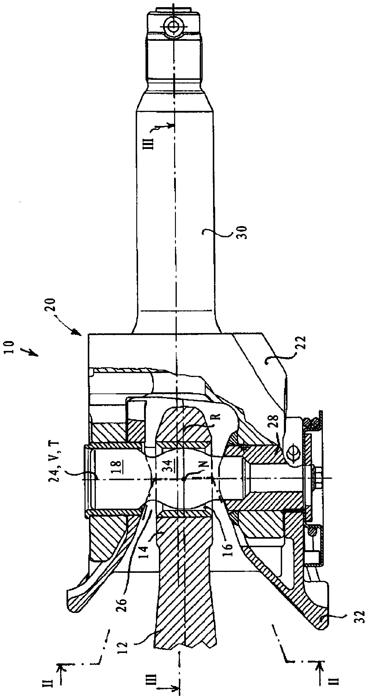
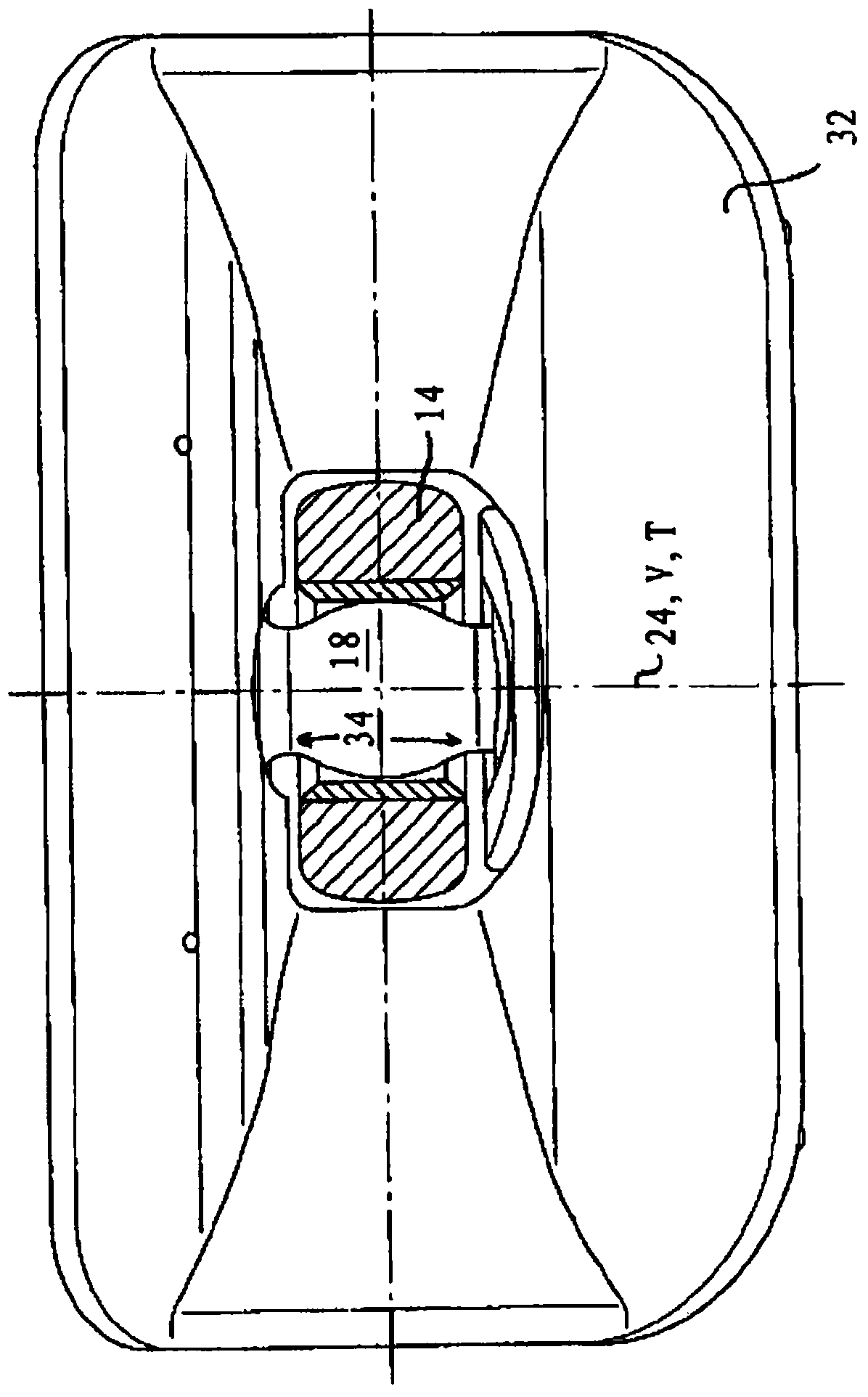
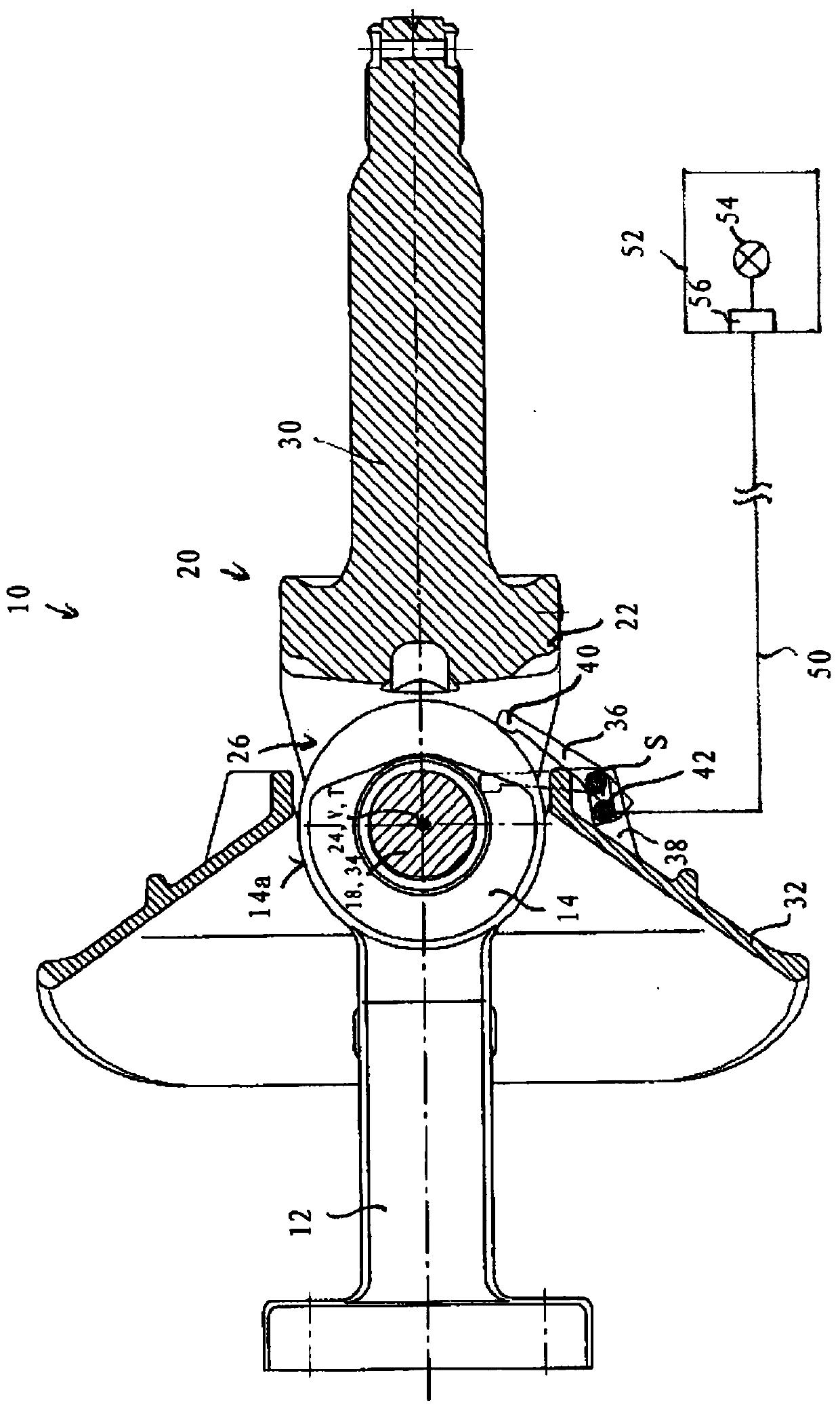
[0047] exist figure 1 In is a first embodiment of the coupling arrangement of the present invention, generally designated 10 . At the same time it is a bolted coupling. In a manner known per se, the coupling arrangement has a tow bar 12 , which is generally fixedly connected to a trailer (not shown in the figures), and a tow eye 14 is arranged at its longitudinal end remote from the vehicle. The circular hole 16 of the traction ring 14 is in figure 1 Passed by a coupling pin 18 in the view. The coupling pin 18 is thus in the coupling position.

[0048] The coupling pin 18 is an integral part of a cardan joint mechanism 20 which is generally fixedly connected to the tractor.

[0049] Universal joint mechanism 20 in figure 1 In the illustrated embodiment there is a coupling body 22, the coupling pin 18 being displaceably accommodated along an adjustment track V generally coincident with the longitudinal axis 24 of the coupling pin between an open position, not shown, and a ...


PUM


Abstract

The present invention relates to a coupling arrangement assembly for detachably coupling a tractor and a trailer, wherein the coupling arrangement assembly comprises: a coupling mechanism (112 , 114) connected to any one of the two vehicles consisting of the tractor and the trailer, and a universal joint mechanism (120) connected to each of other vehicles, wherein the coupling mechanism (112, 114) and the universal joint mechanism (120) serve as connecting means for establishing coupling connection for transmitting at least a pulling force are capable of being preferably shaped to be interlocked with each other and to be decoupled from each other for separation of the coupling connection, wherein the coupling means (112, 114) are within a predetermined coupling position area when interlocked relative to the vehicle having the universal joint mechanism (120). The assembly is characterized in that the coupling arrangement assembly (110) comprises a sensor (142, 144) configured and arranged to detect whether the position of the coupling mechanism (112, 114) relative to the vehicle with the universal joint mechanism (120) is located in the coupling position area.

Description

technical field [0001] The invention relates to a coupling arrangement for detachably coupling a tractor and a trailer, wherein the coupling arrangement comprises: a coupling mechanism connected to any one of two vehicles consisting of the tractor and the trailer and a A universal joint mechanism that is connected to the respective further vehicle, wherein the coupling mechanism and the universal joint mechanism, as a coupling device for producing a joint connection that transmits at least a tensile force, can preferably be coupled to one another in a form-fitting manner and for decoupling These joint joints can be decoupled from one another, wherein the coupling means are located within a predetermined coupling position range relative to the vehicle with the universal joint joint when the joint joint is established. Background technique [0002] A coupling arrangement of this type is known from DE 10 2006 011 676 A1, which has a traction ring as coupling means and a couplin...

Claims


Application Information

Patent Timeline
Patent Type & Authority Patents(China)
IPC IPC(8): G01V8/10G01V3/08
CPCG01V3/08G01V8/10B60D1/02B60D1/363B60D1/62
Inventor 乌多·斯采帕尼克
Owner JOST WERKE GMBH
Why Eureka
Try Eureka