Fluid flow regulator assembly

A fluid flow, fluid technology applied in the field of fluid flow regulator components, which can solve the problem of not providing accurate and repeatable flow

Active Publication Date: 2016-08-03
FLUIDNET CORP
View PDF9 Cites 0 Cited by
  • Summary
  • Abstract
  • Description
  • Claims
  • Application Information

AI Technical Summary

Problems solved by technology

However, these devices do not provide the accurate and r

Method used


Image

  • Fluid flow regulator assembly
  • Fluid flow regulator assembly
  • Fluid flow regulator assembly

Examples


Embodiment Construction

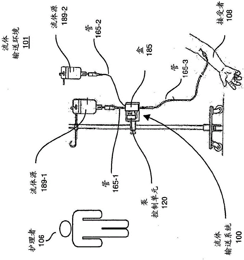
[0038] More specifically, figure 1 is an example diagram illustrating a fluid delivery environment and a fluid delivery system according to embodiments herein.

[0039] As shown, the fluid delivery system 100 disposed in the fluid delivery environment 101 includes a fluid source 189-1 (first fluid source), a second fluid source 189-2 (second fluid source), a pump control unit 120 and a primary Sex tube assembly (eg, the combination of cassette 185, tube 165-1, tube 165-2, and tube 165-3).

[0040] In the example embodiment, cassette 185 has been inserted into a corresponding cavity of pump control unit 120 . Caregiver 106 programs fluid delivery system 100 to deliver fluid to recipient 108 at a desired rate.

[0041] Typically, based on the desired flow rate set by the caregiver 106, during operation, the pump control unit 120 controls corresponding pump resources (e.g., one or more diaphragm pumps), valves, etc. in the cassette 185 to move fluid from the fluid source 189 i...


PUM


Abstract

A fluid flow resistance assembly includes a fluid pathway. A width of the fluid pathway orthogonal to a flow of fluid through the fluid pathway varies along its length. Positioning of one or more ports at different locations over the fluid pathway at different locations controls a flow rate of fluid.

Description

Background technique [0001] Conventional flow regulating devices have been developed to restrict the flow of fluids. A common example is set forth in issued US Patent 3,900,184 entitled "Roller Clamp for Tubing". This type of device relies on the use of common infusion tubing for fluid delivery. Typically, as the rollers are moved from one end of the housing to the other, the tubes within the housing are compressed to restrict the flow of fluid to the intended recipient. [0002] One type of drawback associated with roll clamping techniques is that roll clamping techniques are only capable of very coarse flow adjustments based on the movement of the roll clamps. Another drawback associated with the roll nip technique is that the flow rate setting tends to drift. This is due to the relaxation of the elasticity of the tubing over time leading to an increase in the size of the passageway and a corresponding increase in the flow rate of the conveyed fluid. This creates a poten...

Claims


Application Information

Patent Timeline
IPC IPC(8): A61M5/168A61J1/20
CPCA61M5/16804A61M5/16877A61M5/1408A61M5/16827A61M5/16854A61M5/16881A61M5/36A61M2005/16863A61M2205/3334A61M2205/3337Y10T29/49412B23P15/001F16K3/0209
Inventor J·E·安博罗西娜B·G·鲍尔斯A·J·塞吉特
Owner FLUIDNET CORP
Why Eureka
Try Eureka