
Diversion tunnel plugging structure for initial water storage and rapid plugging method of diversion tunnel

A diversion tunnel, fast technology, applied in the diversion tunnel plugging structure, water conservancy and hydropower construction, the field of diversion tunnel rapid plugging, can solve the problem of weakening the combined bearing effect of temporary plugs and permanent plugs, permanent plug design Long and prolong the construction period, etc., to achieve excellent flow and water-stop performance, reduce construction difficulty, and improve the effect of anti-seepage

Active Publication Date: 2018-03-06
CHINA HYDROELECTRIC ENGINEERING CONSULTING GROUP CHENGDU RESEARCH HYDROELECTRIC INVESTIGATION DESIGN AND INSTITUTE
View PDF7 Cites 2 Cited by
  • Summary
  • Abstract
  • Description
  • Claims
  • Application Information

AI Technical Summary

Problems solved by technology

[0003] (1) The joint surface of the temporary plug and the permanent plug is affected by the temperature stress to produce a dry shrinkage effect, and there may be poor contact, which weakens the combined bearing effect of the temporary plug and the permanent plug, and increases the burden of high external water time risk
Therefore, the design of the permanent plug needs to be longer, which increases the project investment and prolongs the construction period
[0004] (2) Since the initial water storage needs to wait until the permanent plug is poured, the construction period is still long, which affects the power generation efficiency

Method used


Image

  • Diversion tunnel plugging structure for initial water storage and rapid plugging method of diversion tunnel
  • Diversion tunnel plugging structure for initial water storage and rapid plugging method of diversion tunnel
  • Diversion tunnel plugging structure for initial water storage and rapid plugging method of diversion tunnel

Examples


Embodiment

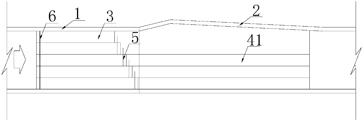
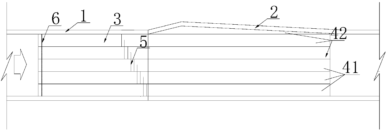
[0036] The above structure can refer to the following design methods:

[0037]The facing surface of the permanent plug is in the shape of an inverted ladder, and is closely combined with the temporary plug 3 . When starting to store water to the dead water level of power generation at the initial stage, the initial water storage plug 41 meets the thickness of each layer of concrete pouring and is the same as the temporary plug, which is 3m / layer. Among them, the pouring length and rising height of the initial water storage plug 41 must meet the requirements of the anti-sliding stability calculation. In the calculation, only the resistance effect of the bottom plate is considered, and the gravity only considers the weight of the poured part. For specific calculation methods, refer to "Code for Design of Hydraulic Tunnels" 》DL / T5195-2004, after calculation, the length of the temporary plug 3 is taken as 20m, and the length of the initial water storage plug 41 and the normal wate...


PUM


Abstract

The invention discloses a rapid diversion tunnel plugging structure capable of shortening construction period. The rapid diversion tunnel plugging structure comprises a diversion tunnel and a plugging body, wherein the diversion tunnel comprises a straight tunnel section and a wedge body section; the plugging body comprises a temporary plug and a permanent plug; the temporary plug is positioned between the permanent plug and a water inlet of the diversion tunnel; and the permanent plug consists of an initial water storage plug positioned on the lower part and a normal water storage plug positioned on the upper part. The permanent plug is divided into the initial water storage plug and the normal water storage plug, so that the permanent plug can be constructed in two stages respectively, namely, initial water storage begins after the temporary plug and the initial water storage plug are constructed by pouring, during initial water storage, the normal water storage plug can be constructed by pouring, through the structure, initial water storage can be carried out in advance, the diversion tunnel is plugged rapidly under the condition of high water head, and initial power generation of a first unit of a hydropower station is implemented ahead of time.

Description

technical field [0001] The invention relates to a water conservancy and hydropower structure, especially a diversion tunnel plugging structure for initial water storage; in addition, the present invention also relates to a water conservancy and hydropower construction method, especially a method for quickly plugging diversion tunnels . Background technique [0002] When constructing high-dam giant hydropower projects in deep mountain and canyon areas, construction diversion usually adopts the method of cofferdam one-time interception + diversion tunnel discharge. In recent years, with the continuous improvement of the construction technology of high dam projects, the rising speed of the dam body has accelerated accordingly. Many projects have the construction image and appearance conditions for the water storage of the gate in advance. If the water storage is carried out in advance, the power generation will undoubtedly increase, and the obtained Huge economic and social be...

Claims


Application Information

Patent Timeline
Patent Type & Authority Patents(China)
IPC IPC(8): E02B9/06E02B3/16
CPCE02B3/16E02B9/06Y02E10/20
Inventor 张超付峥李玉珠何兴勇张有山
Owner CHINA HYDROELECTRIC ENGINEERING CONSULTING GROUP CHENGDU RESEARCH HYDROELECTRIC INVESTIGATION DESIGN AND INSTITUTE
Learn More