Light emitting device and design method of light emitting device
一种发光装置、发光元件的技术,应用在化学仪器和方法、照明装置的零部件、用于改变发射光的光谱特性的光学元件等方向,能够解决色貌考虑不充分等问题
- Summary
- Abstract
- Description
- Claims
- Application Information
AI Technical Summary
Problems solved by technology
Method used
Image
Examples
experiment example 201
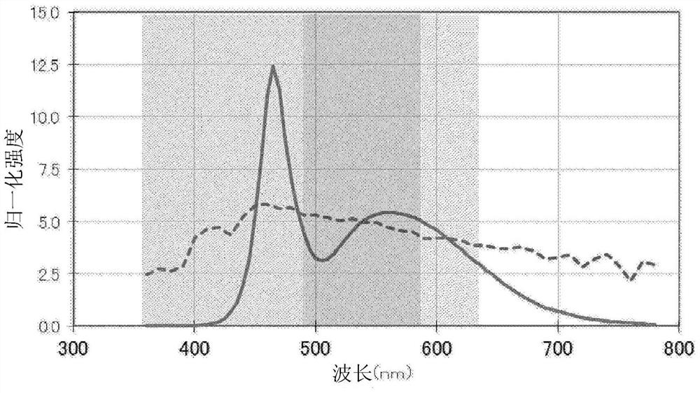
[1086] Such as diagram 2-1As described, a resin package 10 having a diameter of 5 mm and including two light emitting parts in total was prepared. Here, a blue semiconductor light-emitting element (dominant wavelength 452.5nm), a green phosphor (LuAG, peak wavelength 530nm, full width at half maximum 104nm), and a red phosphor (CASN, peak wavelength 645nm, half-value Full width 89nm), and sealed. In addition, the blue semiconductor light-emitting element in the light-emitting region 201 forms a single independent circuit structure to form wiring for encapsulating LEDs, and is connected to a power supply. On the other hand, blue semiconductor light-emitting elements (dominant wavelength 452.5nm), green phosphors (LuAG, peak wavelength 530nm, full width at half maximum 104nm), red phosphors (CASN , peak wavelength 645nm, full width at half maximum 89nm), and sealed. In addition, the blue semiconductor light-emitting element in the light-emitting region 202 constitutes a sing...
experiment example 202
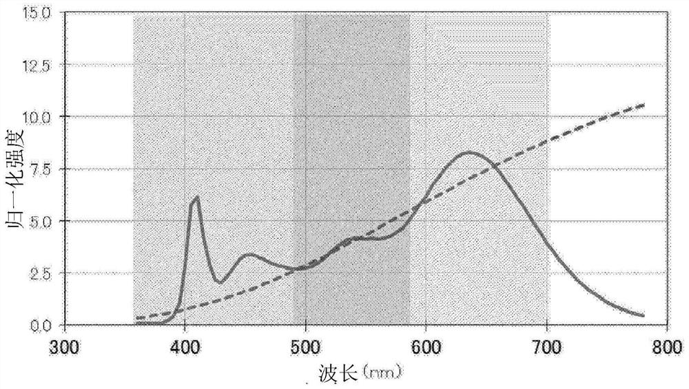
[1099] Such as Figure 2-8 As described above, a ceramic package 20 in which a light emitting portion with a diameter of 7 mm was divided into six small light emitting portions in total was prepared. Here, a blue semiconductor light-emitting element (dominant wavelength 463nm), a green phosphor (LuAG, peak wavelength 530nm, full width at half maximum 104nm), and a red phosphor (CASN, peak wavelength 645nm, 89nm wide) and sealed to form an equivalent light-emitting region. In addition, the semiconductor light emitting elements of the plurality of light emitting regions 221 are connected in series and connected to one independent power supply. On the other hand, blue semiconductor light-emitting elements (dominant wavelength 453nm), green phosphors (LuAG, peak wavelength 530nm, full width at half maximum 104nm), red phosphors (CASN, The peak wavelength is 645nm, the full width at half maximum is 89nm), and it is sealed to form an equivalent light-emitting area. In addition, t...
experiment example 203
[1113] Such as Figure 2-14 As described above, a light-emitting device as a lighting system in which a total of 90 (9×10) light-emitting parts, ie, LED bulbs, were embedded in the top was prepared. Here, an equivalent LED valve is mounted on a solid shaded portion in the figure as the light emitting region 231 to form an equivalent light emitting region. In addition, an equivalent LED valve is mounted as the light-emitting region 232 in the part hatched with a dotted line in the figure, and an equivalent light-emitting region is formed. Here, the LED light bulbs mounted in the plurality of light emitting regions 231 are connected in parallel and combined with one independent power supply. On the other hand, the LED light bulbs mounted in the plurality of light-emitting regions 32 are connected in parallel, and are combined with separate independent power sources. The light emitting region 231 and the light emitting region 232 can be driven independently. In addition, the L...
PUM
| Property | Measurement | Unit |
|---|---|---|
| wavelength | aaaaa | aaaaa |
| wavelength | aaaaa | aaaaa |
| wavelength | aaaaa | aaaaa |
Abstract
Description
Claims
Application Information
 - R&D
- Intellectual Property
- Life Sciences
- Materials
- Tech Scout
- Unparalleled Data Quality
- Higher Quality Content
- 60% Fewer Hallucinations
Browse by: Latest US Patents, China's latest patents, Technical Efficacy Thesaurus, Application Domain, Technology Topic, Popular Technical Reports.
© 2025 PatSnap. All rights reserved.Legal|Privacy policy|Modern Slavery Act Transparency Statement|Sitemap|About US| Contact US: help@patsnap.com


