Driving mechanism for mechanical arm

A technology of driving mechanism and mechanical arm, applied in the direction of manipulator, program-controlled manipulator, manufacturing tool, etc., can solve problems such as the inability to meet modern industrial production

Inactive Publication Date: 2016-08-17
CHANGZHOU JIAYING VEHICLE PART CO LTD
View PDF7 Cites 2 Cited by
  • Summary
  • Abstract
  • Description
  • Claims
  • Application Information

AI Technical Summary

Problems solved by technology

However, in the field of gas cutting, the driving device for the rotation of the mechanical arm has great limitations, which cannot

Method used


Image

  • Driving mechanism for mechanical arm
  • Driving mechanism for mechanical arm
  • Driving mechanism for mechanical arm

Examples


Embodiment Construction

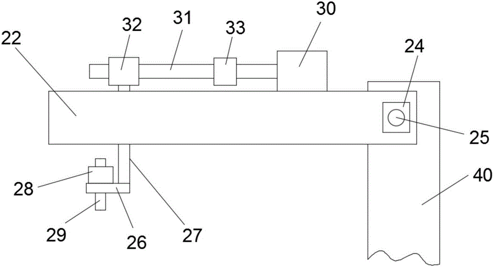
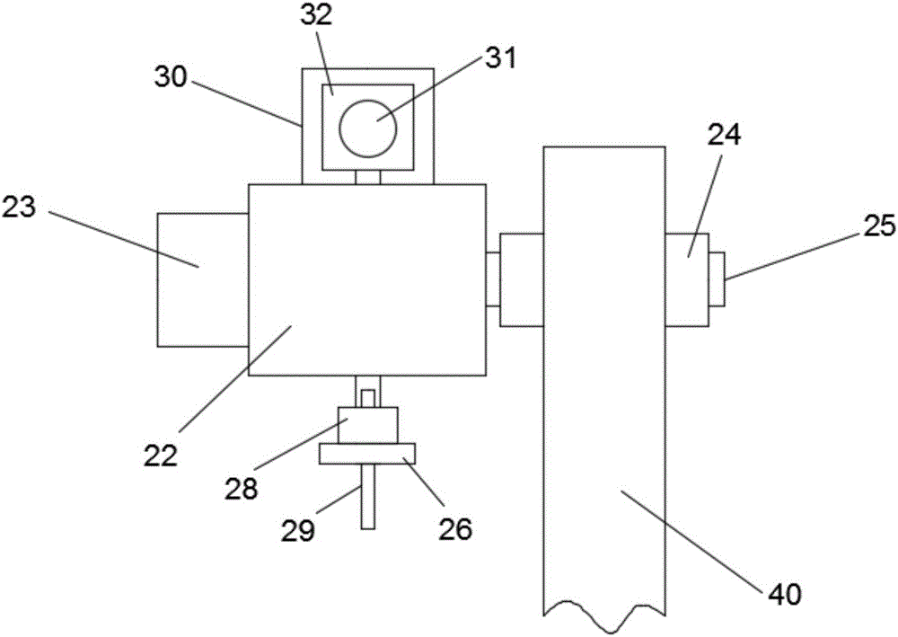
[0020] Such as figure 1 with figure 2 A driving mechanism for a mechanical arm shown includes an upper arm body 40, an upper bracket 22, a connecting rod 27, a support seat 26 and a cutting nozzle joint 29, and the upper bracket 22 is connected to the upper arm body 40 through an angle adjustment mechanism. Above, the upper bracket 22 is provided with a through slot, and the upper end of the connecting rod 27 passes through the slot to connect with the position adjustment mechanism, and the position adjustment mechanism is connected and installed above the upper bracket 22. The support base 26 is connected with the lower end of the connecting rod 27, and the cutting nozzle joint 29 is connected on the support base 26 through the clamping mechanism 28, and a through hole is opened on the support base 26 relative to the position of the cutting nozzle joint 29. During work, start the angle adjustment mechanism to make the upper bracket 22 rotate around the upper arm body 40, co...


PUM


Abstract

The invention relates to a driving mechanism for a mechanical arm. The driving mechanism for the mechanical arm comprises an upper arm body, an upper support, a connection rod, a supporting base and a cutting nozzle joint. The upper support is connected to the upper arm body through an angle adjusting mechanism and provided with a through groove. The upper end of the connection rod penetrates the through groove and is connected with a position adjusting mechanism which is installed above the upper support in a connection manner. The supporting base is connected with the lower end of the connection rod. The cutting nozzle joint is connected to the supporting base through a clamping mechanism. The position, opposite to the cutting nozzle joint, on the supporting base is provided with a through hole. The driving mechanism for the mechanism arm has the beneficial effects of being simple in structure, easy to manufacture, practical and efficient.

Description

technical field [0001] The invention relates to the technical field of mechanical arms, in particular to a driving mechanism for a mechanical arm. Background technique [0002] The robotic arm is the most widely used automatic mechanical device in the field of robotics. It can be seen in industrial manufacturing, medical treatment, entertainment services, military, semiconductor manufacturing, and space exploration. Although their shapes are different, they all have a common feature, that is, they can accept instructions and precisely locate to a certain point in three-dimensional (or two-dimensional) space for operation. The arms generally have three movements: stretching and rotating. and lifting. Realize rotation, lifting movement is to go to finish by cross arm and production column. However, in the field of gas cutting, the driving device for the rotation of the mechanical arm has great limitations, which cannot meet the needs of modern industrial production, so it is...

Claims


Application Information

Patent Timeline
IPC IPC(8): B25J9/00
CPCB25J9/0009
Inventor 谢宏庆
Owner CHANGZHOU JIAYING VEHICLE PART CO LTD
Why Eureka
Try Eureka