Die assembly mechanism for injection molding machine

A technology of mold clamping mechanism and injection molding machine, which is applied in the field of mold clamping mechanism of injection molding machine, and can solve the problems of low mold clamping speed, low efficiency, high energy consumption, etc.

Inactive Publication Date: 2016-08-17
MODERN PRECISION PLASTIC & MOLD SHENZHEN CO LTD
View PDF6 Cites 5 Cited by
  • Summary
  • Abstract
  • Description
  • Claims
  • Application Information

AI Technical Summary

Problems solved by technology

[0003] The purpose of the present invention is to overcome the defects of low mold closing and opening speed, high energy consumption and low efficiency in the prior art, and provide a mold clamping mechanism for injection molding machines, which can effectively reduce energy consumption, improve mold clamping, opening and closing. mold speed

Method used


Image

  • Die assembly mechanism for injection molding machine
  • Die assembly mechanism for injection molding machine
  • Die assembly mechanism for injection molding machine

Examples


Embodiment 1

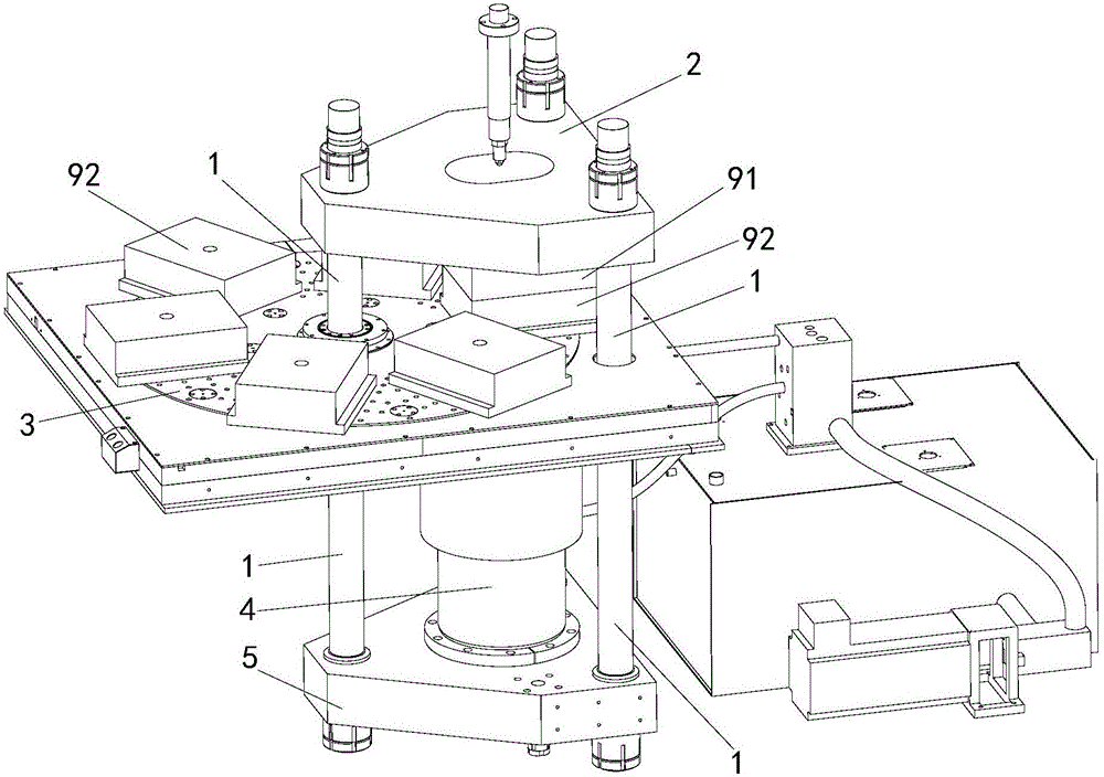
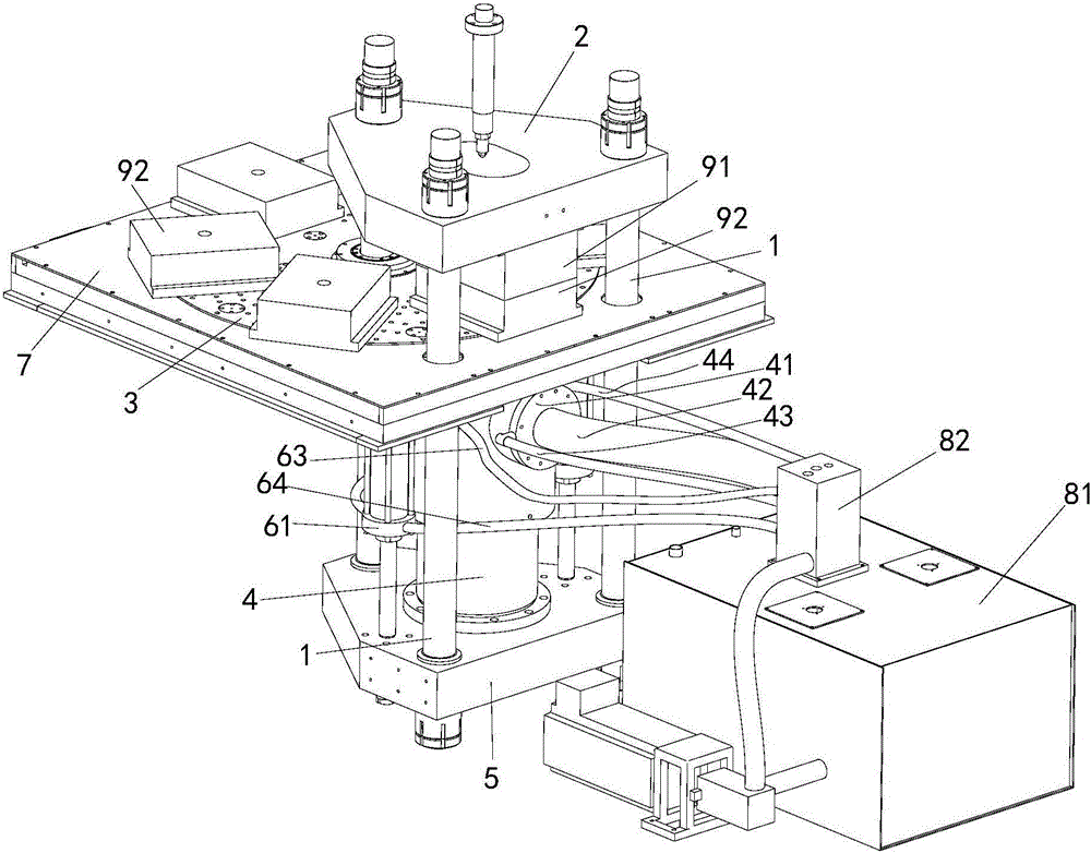
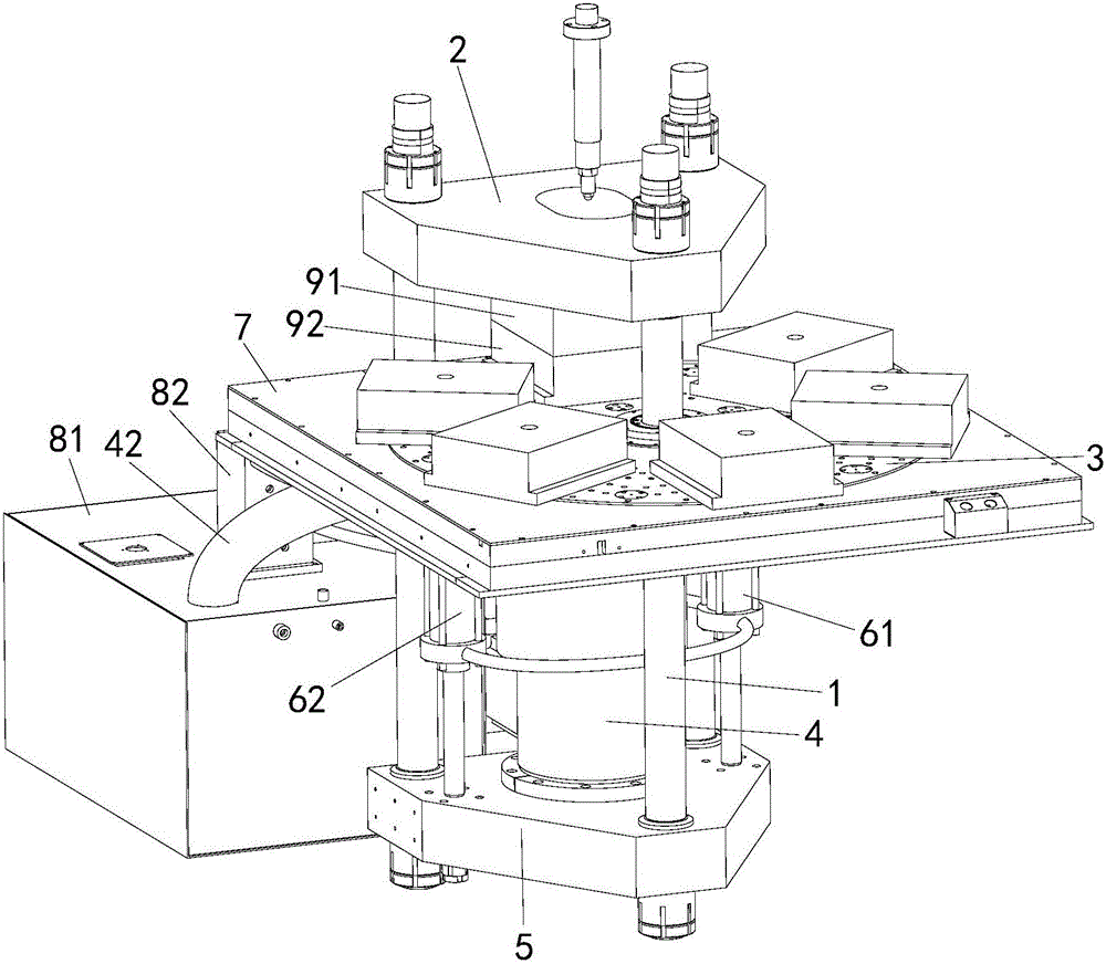
[0025] like Figure 2 to Figure 4 As shown, in this embodiment, the clamping mechanism for the injection molding machine includes: a first fixing plate 2 for fixing the first half mold 91, a second fixing plate 3 for fixing the second half mold 92, an oil cylinder Combination, Corinthian column 1 and the bearing plate 5 carrying the combined force of the oil cylinder, the oil cylinder combination is used to drive the first fixed plate 2 to move down or upward along the length direction of the Corinthian column 1, to realize the connection with the second fixed plate 3 toward or against each other, and then realize the mold closing or mold opening of the first half mold 91 and the second half mold 92. Wherein, the second fixed plate 3 is a rotatable disc, which can be rotated on the frame 7, thereby realizing the replacement of the second half-mold 92 . The oil cylinder combination includes the active oil cylinder 61 / 62 and the slave oil cylinder 4 with the same movement traje...

Embodiment 2

[0033] In this embodiment, it is basically the same as Embodiment 1, except that the slave cylinder 4 includes a hydraulic oil chamber, which includes a pressure oil pipe 44 that communicates with or is disconnected from the high-pressure hydraulic oil pipeline, and is connected with the normal hydraulic oil pipeline. The pressure hydraulic oil is connected or disconnected from the normal pressure oil pipe 42.


PUM


Abstract

The invention discloses a die assembly mechanism for an injection molding machine. The mechanism comprises a first fixing plate, a second fixing plate, an oil cylinder assembly, a drag link and a carrying plate used for carrying the applied force of the oil cylinder assembly, wherein the oil cylinder assembly is used for driving the first fixing plate and the second fixing plate to move, so that the first fixing plate and the second fixing plate move relatively or oppositely to realize die assembly and die disassembly; the oil cylinder assembly comprises a driving oil cylinder and a driven oil cylinder having the same moving track, and the driving oil cylinder is used for driving the die assembly mechanism to realize die assembly and die disassembly movement; during die disassembly, the driven oil cylinder is moved passively; during die assembly, the main journey of the driven oil cylinder makes passive movement, the driven oil cylinder actively makes effort to realize die assembly with larger pressure clamping force after die assembly is about to complete or is completed. According to the die assembly mechanism, the advantages of quick movement of small-diameter driving oil cylinder and large pressure of driven oil cylinder can be sufficiently achieved due to the oil cylinder assembly formed by the driving oil cylinder and the driven oil cylinder, and the time for assembling and disassembling die can be shortened, on the premise that high-pressure die assembling and die locking is sufficiently guaranteed.

Description

technical field [0001] The invention belongs to the technical field of plastic production equipment, in particular to a mold clamping mechanism for an injection molding machine. Background technique [0002] Injection molding machine, also known as injection molding machine or injection machine, is the main forming equipment that can make thermoplastics or thermosetting plastics into various shapes of plastic products using molding molds. The mold clamping mechanism is one of the important parts of the injection molding machine. Its function is to realize the opening and closing movement of the first half mold and the second half mold, and press the first half mold and the second half mold tightly when closing the mold. There are generally two types of mold clamping mechanisms, one is a toggle-type mold clamping mechanism, and the other is a hydraulic direct-lock mold clamping mechanism. The toggle mechanism has the advantages of large stroke, fast moving speed, and low pow...

Claims


Application Information

Patent Timeline
IPC IPC(8): B29C45/67B29C45/06
CPCB29C45/67B29C45/06B29C2045/6785
Inventor 范开贤
Owner MODERN PRECISION PLASTIC & MOLD SHENZHEN CO LTD
Why Eureka
Try Eureka