
Single Cup Injection Mold

An injection mold, single-cup technology, applied in household appliances, other household appliances, household components, etc., can solve problems such as low production efficiency, improve efficiency, and facilitate product release.

Active Publication Date: 2019-07-02
南京益昌模具有限公司
View PDF4 Cites 0 Cited by
  • Summary
  • Abstract
  • Description
  • Claims
  • Application Information

AI Technical Summary

Problems solved by technology

However, this injection mold can only inject one cuvette. When the cuvette needs to be mass-produced, the production efficiency is low.

Method used


Image

  • Single Cup Injection Mold
  • Single Cup Injection Mold
  • Single Cup Injection Mold

Examples


Embodiment Construction

[0026] The present invention will be described in further detail below in conjunction with the accompanying drawings.

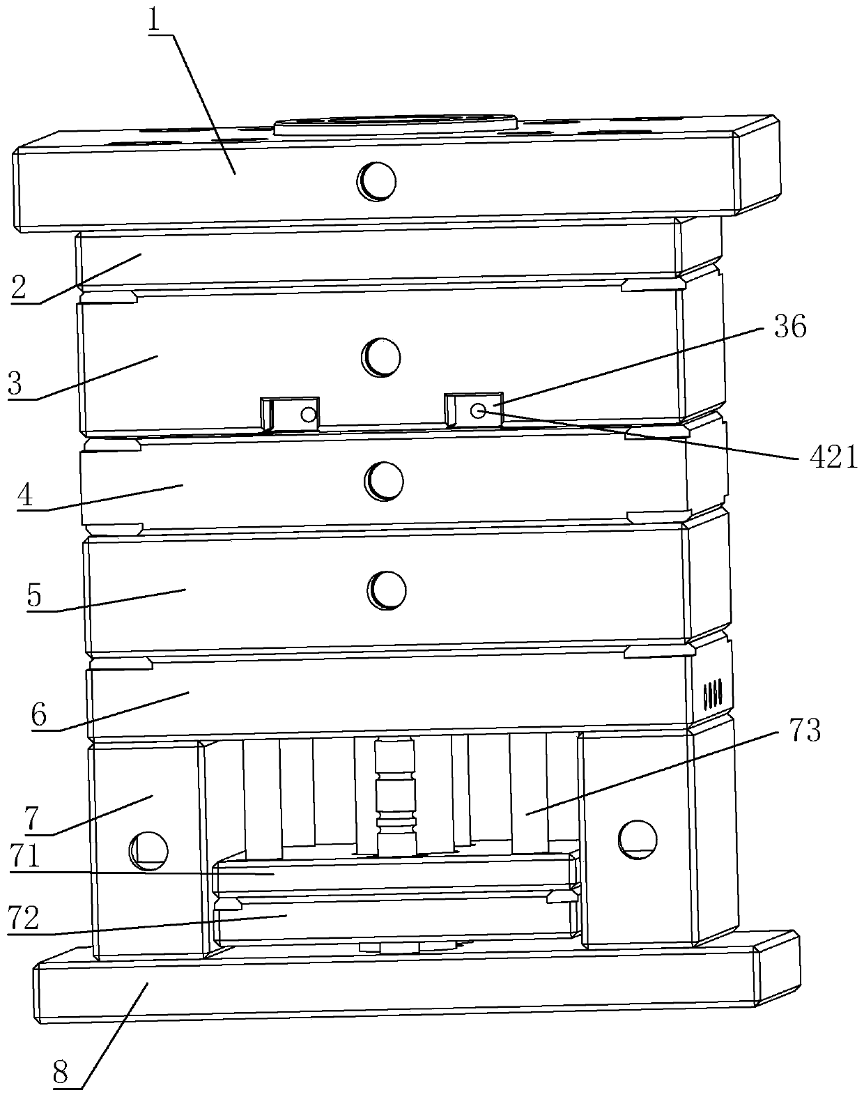
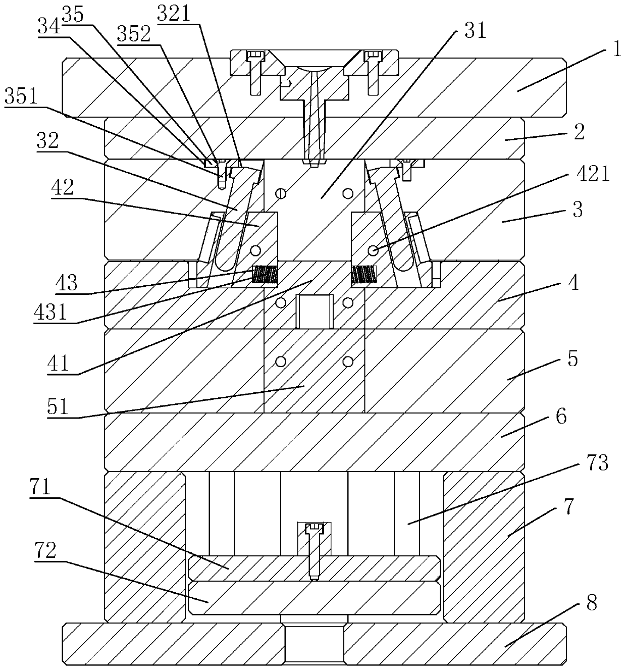
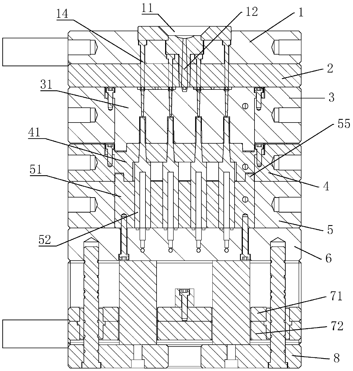
[0027] A single-cup injection mold, such as figure 1 , including: upper fixed plate 1, nozzle plate 2, A plate 3, unloading plate 4, B plate 5, placement plate 6, two support plates 7 supporting the placement plate 6, two support plates located on top to bottom 7 between the push rod fixed plate 71 and the first push plate 72, the lower fixed plate 8 connecting the two support plates 7, as figure 2 , A plate 3 is embedded with a front mold core 31, a second push plate 41 corresponding to the front mold core 31 is embedded in the stripping plate 4, and a rear mold corresponding to the front mold core 31 is embedded in the B plate 5 Kernel 51, the rear mold kernel 51 is provided with a positioning block 55 stretching into the second push plate 41 (such as image 3 ), which is conducive to the accuracy of the movement of the rear mold core 51 and the second p...


PUM


Abstract

The invention discloses a single cup injection mold and relates to the injection mold and aims to provide the single cup injection mold. The single cup injection mold has the advantages that a plurality of reaction cups are produced at a time in an injection molding manner, and production efficiency is improved. According to the technical scheme, the single cup injection mold is characterized in that a front mold core is embedded into a plate A, a second push plate corresponding to the front mold core is embedded into an unloading plate, and a rear mold core corresponding to the front mold core is embedded into a plate B; the positions, on the two sides of the front mold core, of the unloading plate are in slippage connection with row orientation blocks correspondingly, and the positions, in contact with the front mold core, of the row orientation blocks stretch into the front mold core and form cavities of a plurality of single cups with the front mold core; the plate A is internally in slippage connection with guide rods inserted into the row orientation blocks in an inclined manner, the sides, facing the second push plate, of the row orientation blocks are provided with grooves, and the grooves are internally provided with compression springs; and the rear mold core is provided with inserts stretching into all the cavities, an upper fixing plate and a water opening plate are internally provided with injection molding systems, and when the plate A is separated from the water opening plate, the plate B is provided with a drive piece enabling the plate A to be separated from the unloading plate and enabling the upper fixing plate to be separated from the water opening plate.

Description

technical field [0001] The invention relates to an injection mold, in particular to a single-cup injection mold. Background technique [0002] Among the medical low-value consumables, there is a cuvette that is a disposable product. [0003] The Chinese patent with the notification number CN204800977U discloses a reaction cup injection mold, which includes an upper mold, an upper mold base, a lower mold, and a lower mold base. The upper mold is fixed on the lower surface of the upper mold base, and the lower mold is fixed on the lower surface of the upper mold base. On the upper surface of the lower mold base, a positioning mold core is arranged between the upper mold and the lower mold, and the positioning mold core is fixedly installed on the lower surface of the upper mold. There are two glue inlets on both sides of the middle part of the tapered insert, and the glue inlets are symmetrical to the vertical line at the center of the bottom of the tapered insert. However, ...

Claims


Application Information

Patent Timeline
IPC IPC(8): B29C45/32B29C45/27B29C45/33B29C45/40B29C45/73B29L31/00
CPCB29C45/27B29C45/32B29C45/332B29C45/401B29C45/7312B29C2045/2791B29C2045/338B29L2031/753
Inventor 王能光
Owner 南京益昌模具有限公司
Learn More