
Clothes drying machine microswitch control device with roller

A micro switch and control device technology, applied in the direction of clothesline, washing device, other drying devices, etc., can solve the wear and tear of the micro switch drive rod, the lack of clothesline limit mechanism, and the detachment of the micro switch control device and other problems to achieve the effect of avoiding friction, reducing friction, and preventing wire jumping

Inactive Publication Date: 2016-08-17
GUANGDONG A OK TECH GRAND DEV CO LTD
View PDF13 Cites 0 Cited by
  • Summary
  • Abstract
  • Description
  • Claims
  • Application Information

AI Technical Summary

Problems solved by technology

[0002] Most of the micro switch control devices in the prior art use the tension or relaxation of the clothesline to adjust the micro switch driving rod used to control the micro switch, thereby effectively controlling the clothes drying machine. In the actual use process, due to the continuous reciprocating movement of the clothesline, the driving rod of the micro switch is severely worn, which greatly affects the normal operation of the micro switch. In addition, because the micro switch control device lacks the necessary The clothesline limit mechanism makes it easy for the clothesline to jump when it is in a slack state, so that it is separated from the micro switch control device, thereby affecting the normal operation of the clothesline

Method used


Image

  • Clothes drying machine microswitch control device with roller
  • Clothes drying machine microswitch control device with roller
  • Clothes drying machine microswitch control device with roller

Examples


Embodiment Construction

[0019] The technical solutions of the present invention will be further described below in conjunction with the accompanying drawings and through specific implementation methods.

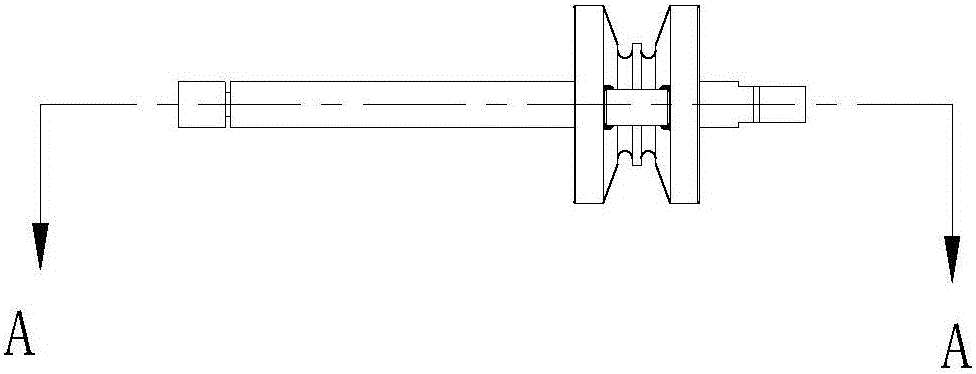
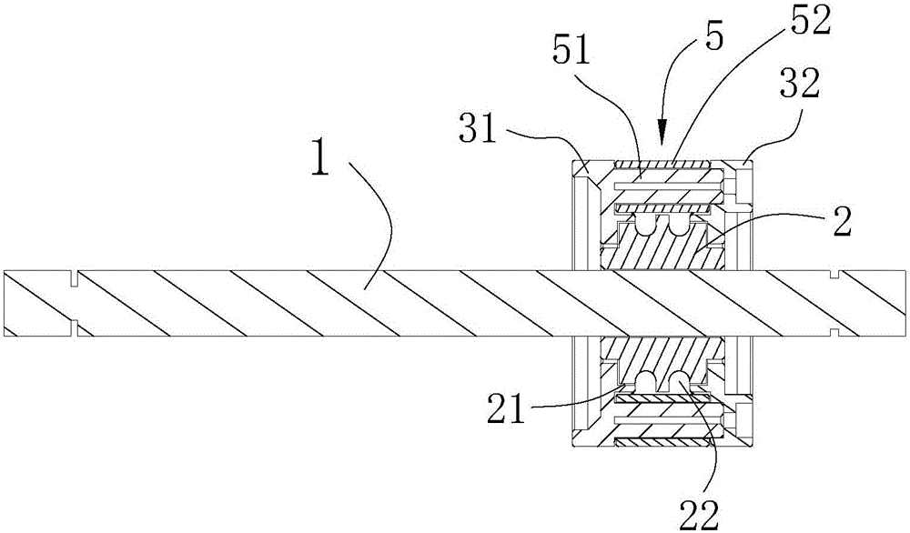
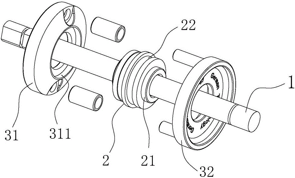
[0020] as attached figure 1 to attach Figure 4 As shown, a clothes dryer micro switch control device with rollers includes a micro switch driving rod 1, and also includes a roller mechanism that slides left and right along the micro switch driving rod 1, and the roller mechanism includes a sleeve The left roller wall 31 and the right roller wall 32 of the micro switch driving rod 1 are sandwiched between the left roller wall 31 and the right roller wall 32 for surrounding the micro switch under the friction of the clothesline 4 The rolling wheel 2 that drives the rod 1 to rotate, and the limit mechanism for preventing the clothesline 4 from detaching from the rolling wheel mechanism.

[0021] Preferably, the scroll wheel 2 is sheathed on the micro switch driving rod 1 and is in clearance fit with...


PUM


Abstract

The invention discloses a clothes drying machine microswitch control device with a roller. The device comprises a microswitch driving rod and further comprises a roller mechanism. The roller mechanism comprises a left roller wall, a right roller wall, the roller and a limiting mechanism, wherein the microswitch driving rod is sleeved with the left roller wall and the right roller wall, the roller is clamped between the left roller wall and the right roller wall and used for rotating around the microswitch driving rod under the friction action of a clothesline, and the limiting mechanism is used for preventing the clothesline from disengaging from the roller mechanism. The roller which rotates around the microswitch driving rod under the friction action of the clothesline can move back and forth along with the clothesline and rotate around the microswitch driving rod, and accordingly friction between the roller and the microswitch driving rod is effectively avoided. Besides, by means of the arrangement of the limiting mechanism, the situation that the clothesline disengages from the roller mechanism in the loose state can be effectively prevented, and accordingly normal work of a clothes drying machine is affected. The microswitch control device can effectively reduce friction between the clothesline and the microswitch driving rod, and jump of the clothesline can be effectively prevented.

Description

technical field [0001] The invention relates to the technical field of laundry machines, in particular to a micro switch control device for a laundry machine with rollers. Background technique [0002] Most of the micro switch control devices in the prior art use the tension or relaxation of the clothesline to adjust the micro switch driving rod used to control the micro switch, thereby effectively controlling the clothes drying machine. In the actual use process, due to the continuous reciprocating movement of the clothesline, the driving rod of the micro switch is severely worn, which greatly affects the normal operation of the micro switch. In addition, because the micro switch control device lacks the necessary The clothesline limit mechanism makes it easy for the clothesline to jump when it is in a relaxed state, so that it is separated from the micro switch control device, thereby affecting the normal operation of the clothesline. Contents of the invention [0003] ...

Claims


Application Information

Patent Timeline
Patent Type & Authority Applications(China)
IPC IPC(8): D06F57/00D06F53/02
CPCD06F57/00D06F53/02
Inventor 汤智文
Owner GUANGDONG A OK TECH GRAND DEV CO LTD
Learn More